Balancing system for an aircraft turbomachine

a turbomachine and balancing technology, which is applied in the direction of machines/engines, sustainable transportation, mechanical equipment, etc., can solve the problems of long and expensive maintenance operations that have to be contemplated on the turbomachine, and all the more restrictive, so as to achieve advantageous facilitation

Active Publication Date: 2020-02-06
SN DETUDE & DE CONSTR DE MOTEURS DAVIATION S N E C M A
View PDF0 Cites 4 Cited by
  • Summary
  • Abstract
  • Description
  • Claims
  • Application Information

AI Technical Summary

Benefits of technology

[0025]The first annular row is arranged downstream of the second annular row. Once again, a reverse situation could be retained, by placing the first row upstream of the second one. However, the importance in placing the first row downstream of the second one resides in its capacity for it to assume a higher diameter, and to further space the first mounting ports apart from each other. The temporary balancing operation, as well as the subsequent rebalancing steps, are consequently advantageously facilitated.

Problems solved by technology

When the maximum balancing capacity is reached, lengthy and expensive maintenance operations have to be contemplated on the turbomachine, as for example a new distribution of the fan blades about the fan disc.
However, conventional designs of balancing systems have the limits reminded above, which turn out on the other hand to be all the more restrictive as the dimensions of the inlet cowl are low.

Method used


Image

  • Balancing system for an aircraft turbomachine
  • Balancing system for an aircraft turbomachine
  • Balancing system for an aircraft turbomachine

Examples


second embodiment

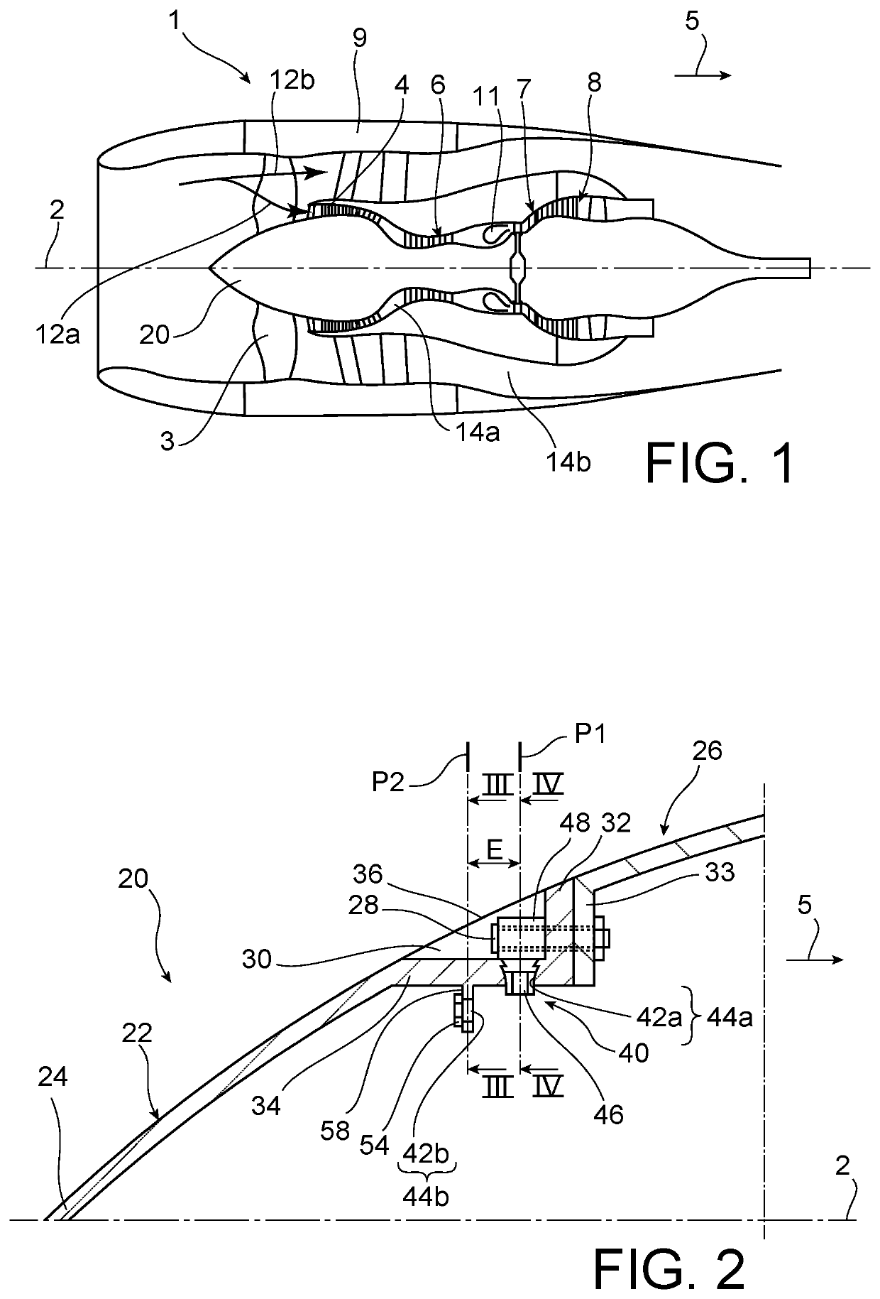
[0076]In this second embodiment, a nose cone 22 extending downstream by a shell 26 is also provided. The fastening clip 33 of the shell 26 is here fastened by bolts 80 to a fan disc 82, partially represented in FIG. 10.

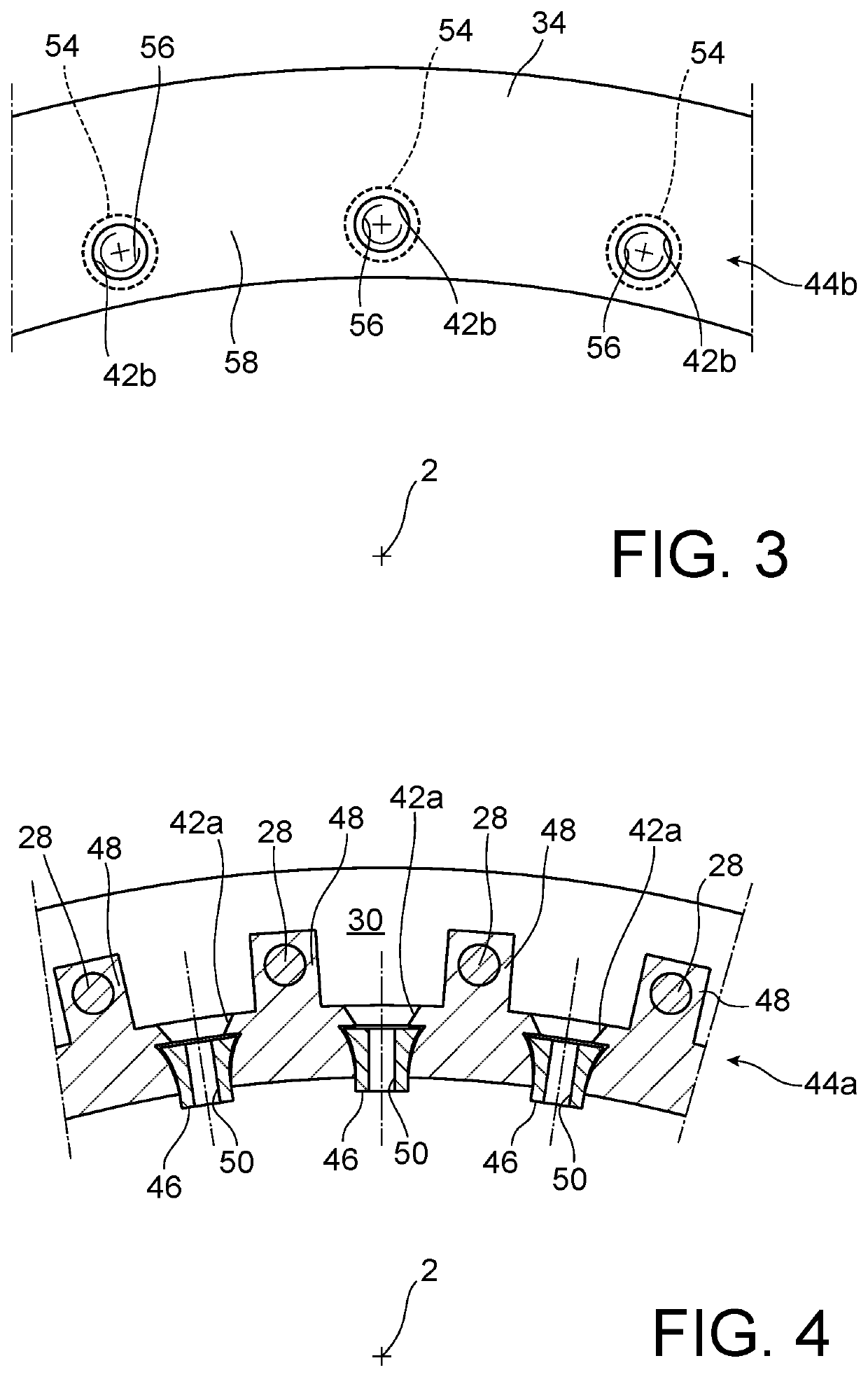
[0077]Another feature of this second embodiment resides in the design of the shell 26, which now integrates an upstream extension 84 projecting axially upstream from the fastening clip 33. The extension 84 includes a first extension part 84a directly adjacent to the clip 33, and axially extending upstream. It is through this first extension part 84a that the first ports 42a are made, each receiving a crimped / captive nut 46 for receiving a first balancing member 60a-60c.

[0078]In the axial continuity of the first extension part 84a, the upstream extension 84 includes a second extension part 84b, through which the second ports 42b of the second annular row 44b are made. Here, the second balancing members take the form of second balance screws 70a-70c, fastened to the se...

first embodiment

[0080]The fastening part 84c and the second extension part 84b are both radially covered with the downstream part of the nose cone 22. This cone 22 terminates at the first extension part 84a, which is not covered with the cone. Consequently, as in the first embodiment, the first mounting ports 42a of the first row 44a remain radially accessible from outside the cone 22 and the shell 26, which facilitates balancing operations on the plane P1.

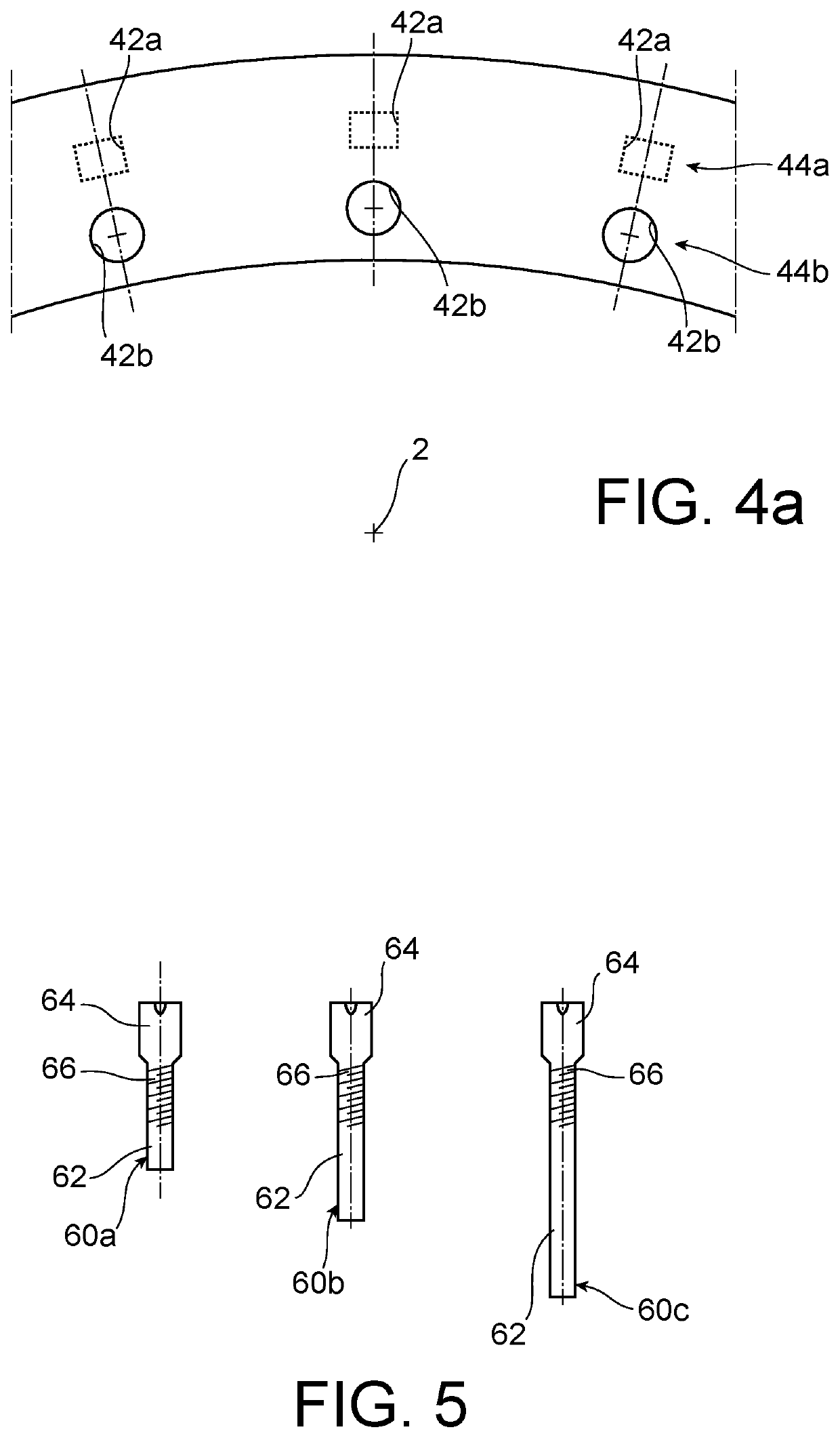
[0081]Indeed, the first extension part 84a comprises the recesses 30 in which the screw heads 64 are located, which thus are also radially accessible from outside the cone 22 and the shell 26. By accessibility, it is meant a direct accessibility in the case where the recesses 30 remain radially outwardly open, but also an indirect accessibility in the case where each recess 30 is closed by an individual aerodynamic cowling 36, readily removable from the first extension part 84a.

[0082]It is also noted that a sealing device, such as an O-ring 88 c...


PUM


Abstract

The invention relates to a balancing system of an aircraft turbomachine comprising a first annular row of first mounting ports for mounting balancing members, and a second annular row of second mounting ports for mounting balancing members which is axially offset from the first annular row, the number and angular positions of the first mounting ports being identical to the number and angular positions of the second mounting ports.

Description

TECHNICAL FIELD[0001]The invention relates to the field of balancing an aircraft turbomachine. It more precisely relates to a turbomachine balancing system, as for example that described in document FR 2 996 255 A1.[0002]The invention is applicable to any type of turbomachine, such as a turbojet engine or a turboprop engine.STATE OF PRIOR ART[0003]A turbomachine is generally equipped with several modules assembled to each other. Prior to this assembly, each module is dynamically balanced so as to reduce its unbalance. After this assembly, it is the turbomachine equipped with all its modules which undergoes a balancing, using a system therefor on a rotary inlet cowl of the turbomachine.[0004]The balancing system conventionally comprises an annular row of mounting ports, in which balancing members have to be mounted. These members can be balance weights, balance screws, or similar elements. By wisely disposing these balancing members in the mounting ports, the overall turbomachine unb...

Claims


Application Information

Patent Timeline
Patent Type & Authority Applications(United States)
IPC IPC(8): F01D25/04F01D25/24
CPCF05D2260/96F01D25/24F05D2230/60F01D25/04F01D5/025F01D5/027F01D5/066F05D2220/36Y02T50/60
Inventor HUGON, NADÈGE PAULINE AUDREYGIRAUDEAU, THOMASPERROLLAZ, JEAN-MARC CLAUDEBATONNET, BAPTISTE RENÉ ROGERLAGARDE, ROMAIN NICOLAS
Owner SN DETUDE & DE CONSTR DE MOTEURS DAVIATION S N E C M A
Why Eureka
Try Eureka