Plug-in connector arrangement

a technology of plug-in connectors and connectors, which is applied in the direction of coupling device details, coupling device connections, electric discharge lamps, etc., can solve the problems of easy damage and unfavorable manner, and achieve the effect of facilitating effective protection of tongues and facilitating koshiri security

Active Publication Date: 2015-12-03
ERNI PRODION GMBH
View PDF0 Cites 5 Cited by
  • Summary
  • Abstract
  • Description
  • Claims
  • Application Information

AI Technical Summary

Benefits of technology

[0006]In contrast, the plug-in connector arrangement according to the invention has the advantage that the snap-in elements comprise at least one snap-in tongue with a snap-in nose that is arranged in the first housing part inside a tongue receiving pocket, wherein the snap-in nose meshes with an opening provided for it inside a housing wall of the second housing part, and that the tongue receiving pocket in the first housing part is formed in the shape of a groove with a substantially U-shaped cross-section, wherein the two lateral U-legs protrude beyond the tongue. With the two lateral U-legs protruding in this manner, a particularly effective protection of the tongue is facilitated, as the tongue that is positioned between the two U-legs cannot readily be “bent outward”, for example.
[0007]Advantageous further developments and enhancements of the plug-in connector arrangement that is indicated in the independent claim are the subject matter of the dependent claims. Thus, on the plug side, the two U-legs preferably and particularly advantageously reach up to the front side of the one housing part. Thanks to this arrangement, Koshiri security is particularly advantageously facilitated. That is to say, the two U-legs, reaching up to the front side of the plug and laterally protruding beyond the tongue arranged in between them, do not only protect the tongue in the unlocked state of the plug-in connector arrangement, but they also very effectively prevent any mismating or any canted plug-in of the two plug-in connector parts, which may result in damage to the contact elements arranged therein.
[0008]Advantageously, guide grooves for the two U-legs are provided in the second housing part.
[0009]Moreover, these guide grooves also reach up to the front side of the second housing part in a very advantageous manner. As far as Koshiri security is concerned, these two guide grooves that reach up to the front side of the second housing part are, as it were, the counterpart of the two U-legs. They, too, do not only prevent any mismating, but in particular also prevent any canted mating, which may result in damage to the contact elements.
[0010]At the same time, together with the two U-legs as well as the U-shaped grooves in the mated state of the two plug-in connector parts, the guide grooves limit the tongue receiving pocket in the second plug-in connector part, thus forming the tongue receiving pocket inside of which the tongue comes to rest in the mated state of the two plug-in connector parts.
[0011]The tongue is advantageously formed in a spring-like manner and is advantageously formed as an integral part of one of the two housing parts.

Problems solved by technology

However, in the unlocked state, the tongue protrudes freely from the socket, thus being easily exposed to damage.
Also in this case, the spring shackle—even though it is formed as an integral part of the coupler housing—protrudes from the coupler housing and thus can be damaged if handled in an unfavorable manner.

Method used


Image

  • Plug-in connector arrangement
  • Plug-in connector arrangement
  • Plug-in connector arrangement

Examples


Embodiment Construction

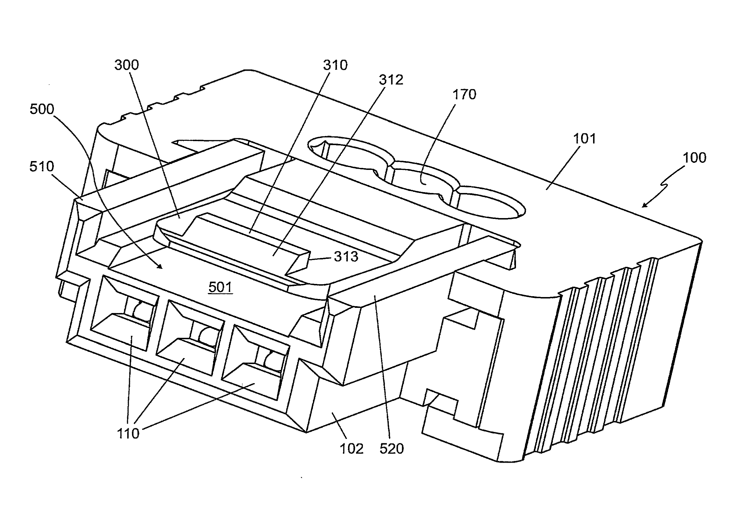
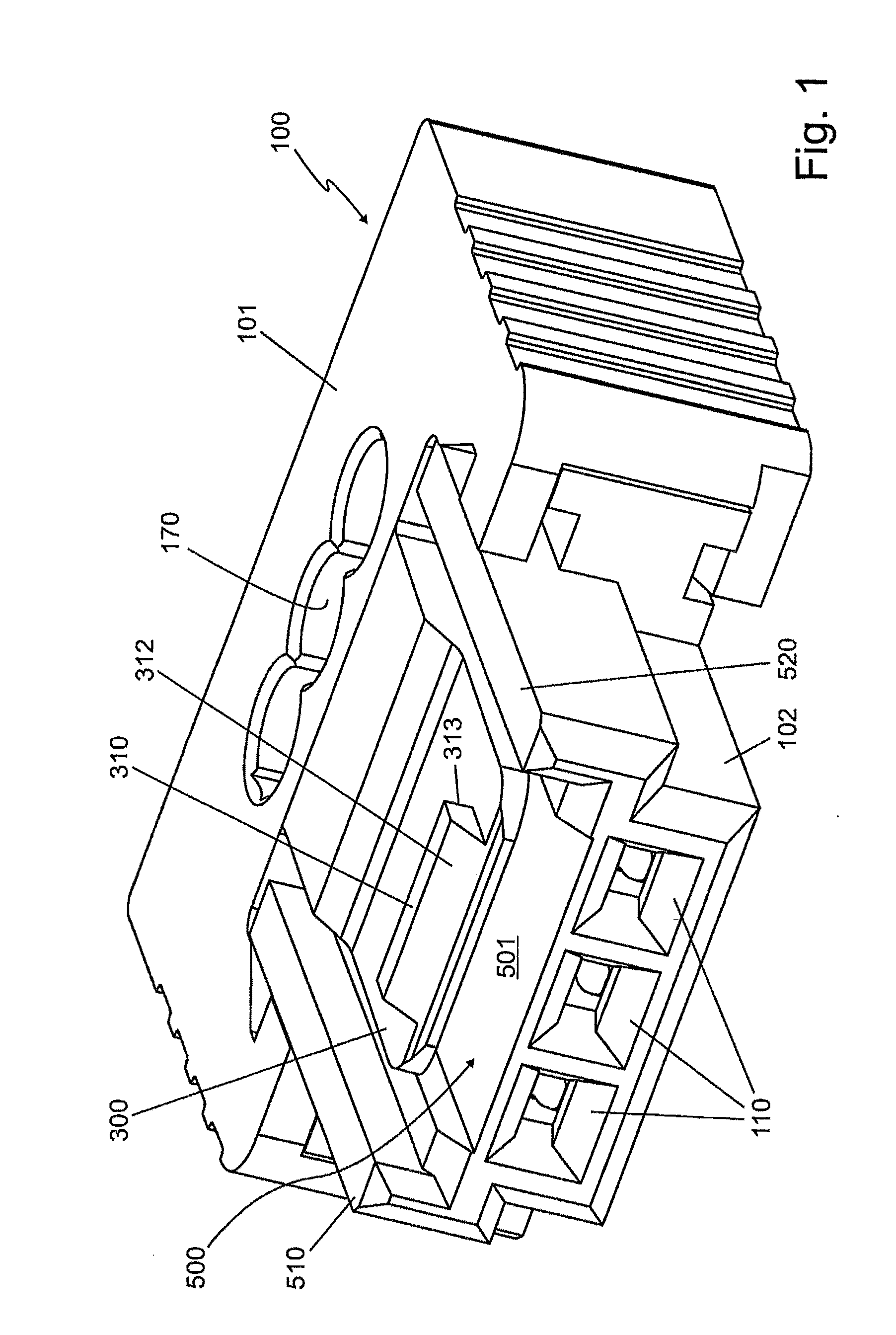
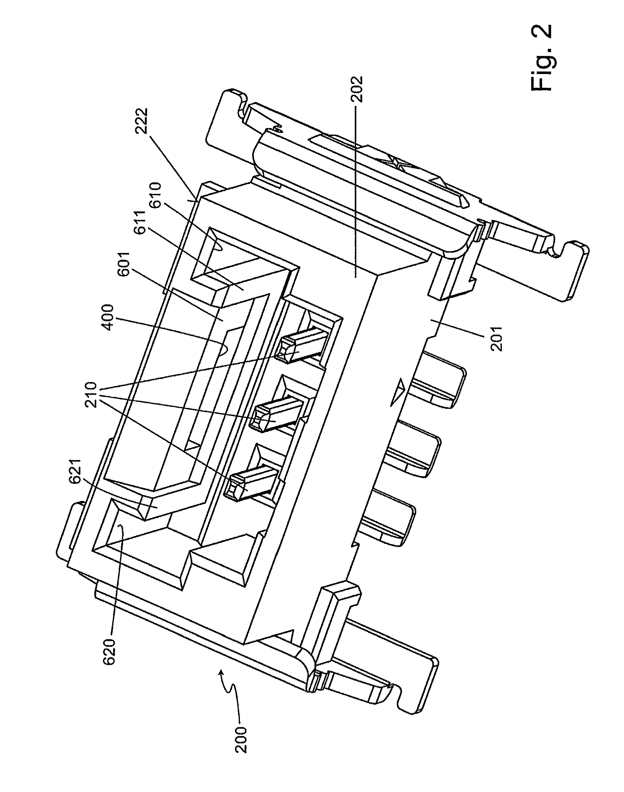
[0018]A plug-in connector arrangement shown in FIG. 1, FIG. 2 and FIG. 3 comprises two plug-in connector parts 100, 200. The one plug-in connector part 100 can be formed as a female multipoint connector, for example, whereas the other plug-in connector part 200 is formed as a multipole plug-in connector, as shown. For this purpose, spring contact elements 110 are provided in a plug-in part 102 of the housing 101 in the plug-in connector part 100 that is formed as a female multipoint connector. In contrast, in a corresponding housing part 202 of the housing 201, knife contact elements 210 are arranged inside the plug-in connector part 200 that is formed as a multipole plug-in connector. The knife contact elements 210 can be plugged into correspondingly adjusted spring contact elements 110 of the plug-in connector part 100.

[0019]A snap-in tongue 300 (which will also be referred to in short as a “tongue” in the following) comprising a snap-in nose 310 is arranged substantially above an...


PUM


Abstract

A plug-in connector arrangement includes two plug-in connector parts which can be plugged into each another and which each have a housing part, the housing parts being adapted to each another, and a plug contact provided therein, the plug contacts being adapted to each another, wherein the two housing parts have detent elements for detachably connecting the two housing parts to each other. The detent elements include at least one detent tongue that has a detent lug and is arranged in a tongue-receiving pocket in the first housing part, the detent lug engaging in an opening provided therefor in a housing wall of the second housing part, and the tongue-receiving pocket in the first housing part is in the form of a groove that has a substantially U-shaped cross-section, the two lateral limbs of the U projecting beyond the detent tongue.

Description

[0001]The invention relates to a plug-in connector arrangement, comprising two intermateable plug-in connector parts according to claim 1.[0002]STATE OF THE ART[0003]Such plug-in connector arrangements exist in different designs. What is known from DE 10 2004 054 203 A1 is an insulation-displacement connector plug contact strip for electrical plug-in connectors, comprising combined connection elements which form an insulation-displacement connector area for a stripping-free connection of electrical conductors at one end, and form a plug contact area for a plug contact mating bar at the other end, wherein flat, slotted insulation-displacement connectors are supported on the insulation-displacement connector area. The connection elements are formed in such a manner that the insulation-displacement connectors of these connection elements lie in multiple rows in the insulation-displacement cable connector for a row of plug contacts of the connection elements that are embedded next to ea...

Claims


Application Information

Patent Timeline
Patent Type & Authority Applications(United States)
IPC IPC(8): H01R13/506
CPCH01R13/506H01R13/6272H01R13/64
Inventor LAPPOEHN, JUERGEN
Owner ERNI PRODION GMBH
Why Eureka
Try Eureka