3D panoramic vision device for unmanned aerial vehicle

A panoramic vision and drone technology, applied in the field of 3D panoramic vision devices for drones, can solve the problems of difficulty in 3D modeling of the surrounding environment, low level of automation and intelligence, etc.

Inactive Publication Date: 2015-12-30
汤一平
View PDF8 Cites 45 Cited by
  • Summary
  • Abstract
  • Description
  • Claims
  • Application Information

AI Technical Summary

Problems solved by technology

[0008] In order to overcome the low level of automation and intelligence of the existing UAV vision devices, it is difficult to quickly measure the surrounding scenes and objects in 3D, it is difficult to quickly detect and avoid obstacles in the surrounding environment by visual means, and the 3D construction of the surrounding environment Insufficiencies such as difficult modeling, the present invention provides a novel 3D panoramic vision device for unmanned aerial vehicles, which can improve the automation and intelligence level of the unmanned aerial vehicle visual device, and perform rapid 3D visual measurement of the surrounding environment and objects of the unmanned aerial vehicle, and Automated 3D modeling

Method used


Image

  • 3D panoramic vision device for unmanned aerial vehicle
  • 3D panoramic vision device for unmanned aerial vehicle
  • 3D panoramic vision device for unmanned aerial vehicle

Examples


Embodiment 1

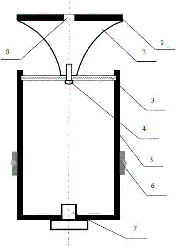
[0127] refer to Figure 1-15 , a new type of unmanned aerial vehicle 3D panoramic vision device mainly includes the main part of the aircraft, the 3D panoramic vision device and the control system part of the ground station of the flight control machine. The 3D panoramic vision device is fixedly installed in the middle of the main part of the aircraft, and the central axis of the 3D panoramic vision device overlaps with the central axis of the main part of the aircraft, such as Figure 8 shown.

[0128] The main part of the aircraft adopts the structure of a quadrotor aircraft, such as Figure 7 As shown; considering the weight and strength of the fuselage, the fuselage adopts a full carbon fiber structure, which is composed of a center plate, arms and landing gear. The center plate is a regular quadrilateral, and the four machine arms are distributed at the fixed points of the quadrilateral of the center plate. The fuselage material is made of 2.0mm thick 3K full carbon pl...

Embodiment 2

[0207]All the other are identical with embodiment 1, and difference is to calculate rotation matrix R and T method from essential matrix E; The method is: first, utilize the attribute of essential matrix E rank 2 to obtain the translation amount t between unmanned aerial vehicle flight, As shown in formula (16);

[0208] t = - e i 2 Me k 2 ...

Embodiment 3

[0218] The rest are the same as in Embodiment 1, except that the 3D reconstruction of the space environment is carried out directly from the motion trajectory of the detected drone; if a GPS positioning device and a height sensor are configured on the drone, then it can be obtained directly from the sensor The spatial position information of the observation point of the UAV, the 3D modeling process of the surrounding environment of the UAV does not need to perform the motion estimation step of the UAV, but directly uses the panoramic point cloud data and panoramic image data of the measurement point, and integrates the GPS positioning device and 3D modeling of UAV space position information from height sensor.


PUM


Abstract

The invention discloses a 3D panoramic vision device for an unmanned aerial vehicle. The 3D panoramic vision device comprises an aircraft main body part, a 3D panoramic vision device body and a flight control machine ground-station control system part, wherein the 3D panoramic vision device body is fixedly mounted in the middle of the aircraft main body part; the axes of the 3D panoramic vision device and the aircraft main body part are overlapped; the 3D panoramic vision device body comprises an omni-directional vision sensor, a panoramic laser light source and an LED strip light source; a ground monitor performs 3D measurement and 3D modeling treatment on the surroundings of the unmanned aerial vehicle according to panoramic video images transmitted by a wireless communication network.

Description

technical field [0001] The invention relates to the application of unmanned helicopters, panoramic laser light sources, omnidirectional visual sensors, wireless transmission and computer vision technology in drone vision, and in particular to a 3D panoramic vision device for drones. Background technique [0002] Aerial photos taken by unmanned helicopters have the advantages of large scale, wide viewing angle, and high visibility. At present, UAV aerial photography is widely used in military reconnaissance, national ecological environment protection, mineral resource exploration, marine environment monitoring, land use investigation, water resource development, crop growth monitoring and yield estimation, agricultural operations, natural disaster monitoring and evaluation, urban planning and Municipal management, forest pest protection and monitoring, public security, national defense, digital earth, advertising photography and other fields have broad market demand. [0003...

Claims


Application Information

Patent Timeline
Patent Type & Authority Applications(China)
IPC IPC(8): G01C11/00
CPCG01C11/00
Inventor 汤一平
Owner 汤一平
Why Eureka
Try Eureka