Compositions and methods for completing subterranean wells

a technology of subterranean wells and compositions, applied in the direction of wellbore/well accessories, fluid removal, earthwork drilling and mining, etc., can solve the problems of premature termination of the completion process, preventing further fluid flow in the wellbore, and excessive fluid loss, so as to reduce the amount of fluid ingress.

Inactive Publication Date: 2016-06-28
SCHLUMBERGER TECH CORP
View PDF25 Cites 40 Cited by
  • Summary
  • Abstract
  • Description
  • Claims
  • Application Information

AI Technical Summary

Benefits of technology

[0013]The first aspect of the invention is a composition for providing fluid-loss control in a subterranean well. The composition comprises a particulate additive, such as a fine particulate thermoplastic or wax, which becomes deformable at temperatures lower than the bottomhole temperature. Upon injection into the well, the additive particles become deformable and, upon migration to and deposition onto the borehole wall, form a seal that reduces further fluid ingress into the formation.
[0014]The second aspect of the invention is a method for controlling fluid loss in a subterranean well. The method comprises preparing a process fluid comprising a composition described by the first aspect of the invention, and pumping the process fluid into the well. After injection into the well, the particulate additive of the composition becomes deformable at a temperature below the bottomhole temperature and migrates to the borehole wall, thereby forming a seal that reduces fluid ingress through the borehole wall and into the formation.

Problems solved by technology

As a result, the liquid portion of the fluid has a tendency to enter pores in the subterranean rock, migrate away from the wellbore, and leave the solid particles behind.
Excessive fluid loss may have undesirable consequences.
For example, as more and more liquid exits the wellbore and penetrates the subterranean rock, the solids left behind may concentrate and form a plug, preventing further fluid flow in the wellbore and terminating the completion process prematurely.
Disruption of the optimal liquid-solid ratio arising from fluid loss may have a detrimental effect on the completion process and cause failure.
Such additives often dissolve or melt after a stimulation treatment, leaving little or no residue behind.
Formation damage is less relevant in the context of well-construction fluids, mainly because the solids content of these fluids is far higher than that of well-stimulation fluids.
The cement systems described herein, as well as other process fluids, are subject to fluid-loss difficulties.

Method used


Image

  • Compositions and methods for completing subterranean wells

Examples


example 1

[0033]The effect of temperature on the ability of a paraffin-wax suspension (Michem Lube 743.E from Michelman, Inc.) to provide fluid-loss control was determined by testing the cement-slurry formulation given in Table 1.

[0034]

TABLE 1Slurry design for evaluating the effect of temperature on thefluid-loss-control performance of a paraffin-wax suspension.Slurry density1890 kg / m3Class G cement100%Silicone antifoam2.7 L / metric ton of solid blendPolynaphthalene sulfonate6.7 L / metric ton of solid blenddispersantParaffin wax suspension88.8 L / metric ton of solid blend*Copolymer of0.1% by weight of cementacrylamido-methyl-propanesulfonate and acrylamideSodium alkylethersulfate0 or 4.4 L / metric ton of solid blendsurfactant*88.8 L / metric ton corresponds to 19.3% by volume of the liquid phase in the cement slurry, or about 6.2% of solid wax by weight of the liquid phase of the cement slurry.

[0035]Michem Lube 743.E contains 32 wt % solids. The melting point of the paraffin-wax particles was 60° C...

example 2

[0037]The ability of a polyethylene-wax suspension to provide fluid-loss control at elevated temperatures was determined by testing ME91240.E from Michelman, Inc., whose properties are described in Example 2. The cement-slurry formulation is given in Table 4.

[0038]The ability of polyethylene-wax suspensions to provide fluid-loss control at ambient temperature was determined by testing two products: ME91240.E and ME93335.E, both from Michelman, Inc. ME91240.E contains 40 wt % solids. The polyethylene-wax particles in ME91240.E have a melting point of 125° C. and a nominal particle size of 0.125 micrometers. ME93335.E contains 35 wt % solids. The polyethylene-wax particles in ME93335.E have a melting point of 138° C. and a nominal particle size of 0.04 micrometers. The cement-slurry formulation is given in Table 3.

[0039]

TABLE 3Slurry design to evaluate the effect of temperature on the fluidloss control performance of polyethylene-wax suspensions.Density1890 kg / m3Class G cement100%Sili...

example 3

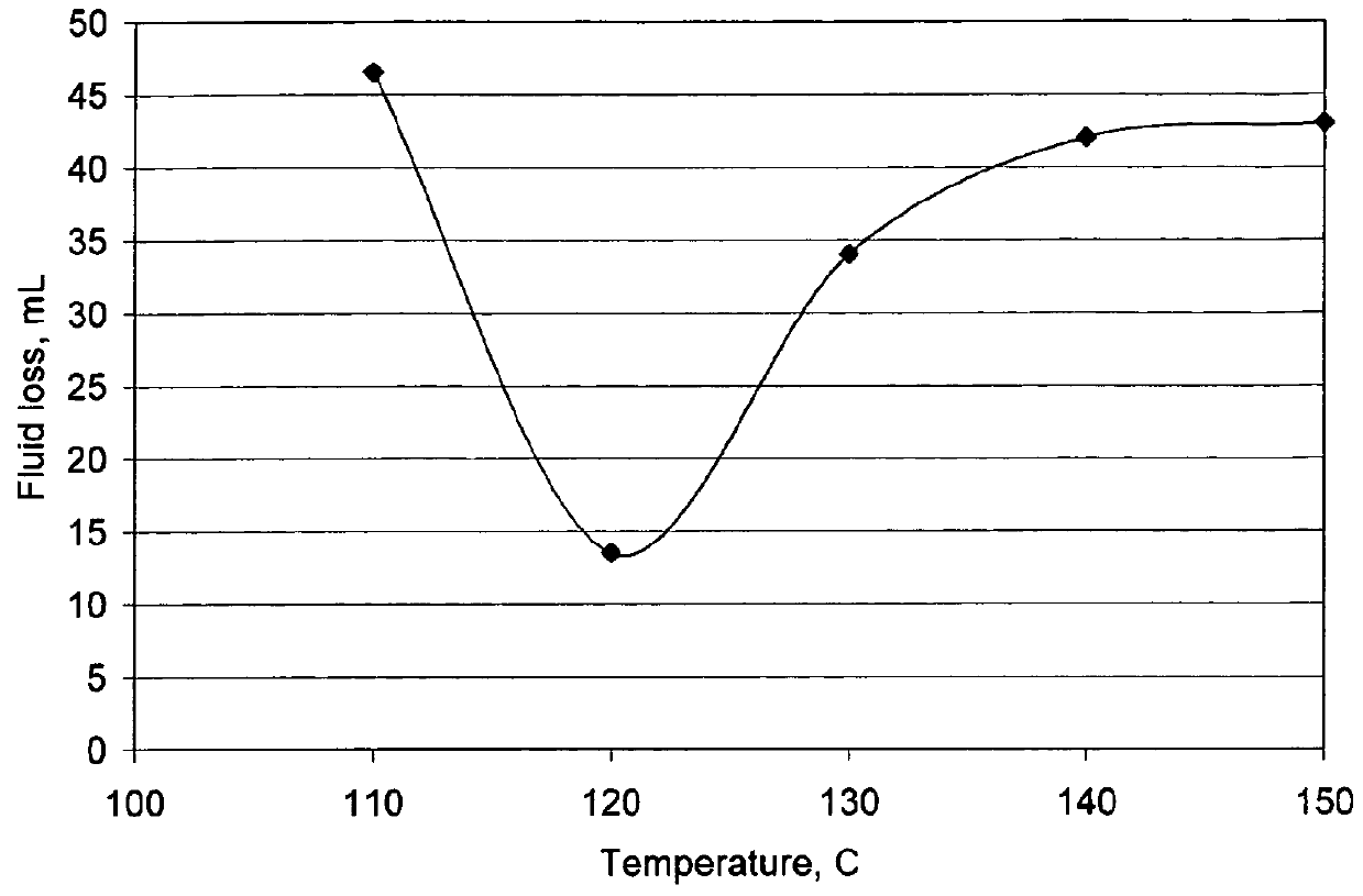
[0040]The ability of a polyethylene-wax suspension to provide fluid-loss control at elevated temperatures was determined by testing ME91240.E from Michelman, Inc., whose properties are described in Example 2. The cement-slurry formulation is given in Table 4.

[0041]

TABLE 4Slurry design to evaluate the effect of temperature on the fluidloss control performance of a polyethylene-wax suspension.Density1890 kg / m3Class G cement100%Silica flour35% by weight of cementSilicone antifoam2.7 L / metric ton of solid blendPolynaphthalene sulfonate0.15% by weight of cementdispersantSodium glucoheptonate0.45% by weight of cementretarderHigh-temperature0.4% by weight of cementlignosulfonate / gluconateretarderPolyethylene wax suspension88.8 L / metric ton of solid blend*Copolymer of0.1% by weight of cementacrylamido-methyl-propanesulfonate and acrylamideSodium alkylethersulfate4.4 L / metric ton of solid blendsurfactantBiopolymer anti-settling0.015% by weight of cementagent (welan gum)*88.8 L / metric ton cor...


PUM

PropertyMeasurementUnit
particle sizeaaaaaaaaaa
melting temperatureaaaaaaaaaa
particle sizeaaaaaaaaaa

Abstract

Disclosed are compositions and methods for providing fluid-loss control in subterranean wells. Well-completion fluids contain fine particulate additives whose glass-transition temperatures are below the anticipated bottomhole temperature. The particles soften upon injection into the well, whereupon they soften and become deformable. The particles then migrate to the borehole wall and form a seal that reduces further fluid flow from the borehole into the formation. The additive may be supplied as a powder or in the form of a liquid suspension.

Description

BACKGROUND OF THE INVENTION[0001]The statements in this section merely provide background information related to the present disclosure and may not constitute prior art.[0002]This invention relates to compositions and methods for completing subterranean wells, in particular, fluid compositions and methods for completion operations during which the fluid compositions are pumped into a wellbore and make contact with subterranean rock formations.[0003]In the course of completing oil and gas wells and the like, various types of fluids are circulated in the wellbore. These fluids will hereinafter be called “process fluids.” Process fluids include, but are not limited to, drilling fluids, spacer fluids and cement slurries. In addition, these fluids typically contain solid particles. Fluid hydrostatic pressure and pumping pressure create a pressure differential between the wellbore and the surrounding formation rock. As a result, the liquid portion of the fluid has a tendency to enter pore...

Claims


Application Information

Patent Timeline
Patent Type & Authority Patents(United States)
IPC IPC(8): C09K8/08C09K8/12C04B28/08C04B28/06C04B28/00C04B28/02C09K8/508C09K8/516C09K8/487C04B103/00C04B103/46C04B111/00
CPCC09K8/08C04B28/006C04B28/02C04B28/06C04B28/08C09K8/12C09K8/487C09K8/508C09K8/516C04B20/008C04B24/36C04B24/08C04B2103/0065C04B2103/46C04B2111/00146Y02P40/165Y02P40/10
Inventor JAMES, SIMON
Owner SCHLUMBERGER TECH CORP
Why Eureka
Try Eureka