Encoding device, decoding device, encoding method and decoding method

a technology of encoding device and decoding method, which is applied in the field of encoding device, encoding device, coding method and decoding method, which can solve problems such as sound quality degradation, and achieve the effect of high-quality extension band spectrum

Active Publication Date: 2016-07-05
PANASONIC INTELLECTUAL PROPERTY CORP OF AMERICA
View PDF23 Cites 8 Cited by
  • Summary
  • Abstract
  • Description
  • Claims
  • Application Information

AI Technical Summary

Benefits of technology

[0026]According to the present invention, a low band part having a sufficiently-lowered peaking property is copied to a high band part (extension band) to prevent generation of a spectrum having an excessively-high peaking property in the high band part, which in turn, enables generation of a high-quality extension band spectrum.

Problems solved by technology

In other words, in the high band part, high peaks are less likely to appear locally compared to the low band part, and thus, copying a signal having a high peaking property to the high band part (extension band) may result in sound quality deterioration.

Method used


Image

  • Encoding device, decoding device, encoding method and decoding method
  • Encoding device, decoding device, encoding method and decoding method
  • Encoding device, decoding device, encoding method and decoding method

Examples


embodiment 1

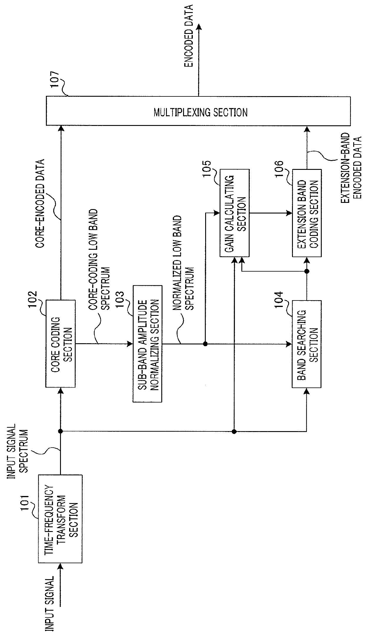
[0052]FIG. 1 is a block diagram illustrating a configuration of coding apparatus 100 according to Embodiment 1.

[0053]Coding apparatus 100 in FIG. 1 includes time-frequency transform section 101, core coding section 102, sub-band amplitude normalizing section 103, band searching section 104, gain calculating section 105, extension band coding section 106 and multiplexing section 107. In the present embodiment, core coding section 102 encodes a low band part (low band spectrum) of an input spectrum that is input to coding apparatus 100, the low band part being of a frequency equal to or lower than a predetermined frequency, and extension band coding section106 encodes a spectrum in a high band of the input spectrum, the high band being higher than the band subjected to the encoding by core coding section 102 (band higher than the predetermined frequency; hereinafter referred to as “extension band”).

[0054]Time-frequency transform section 101 transforms an input time-domain signal (incl...

embodiment 2

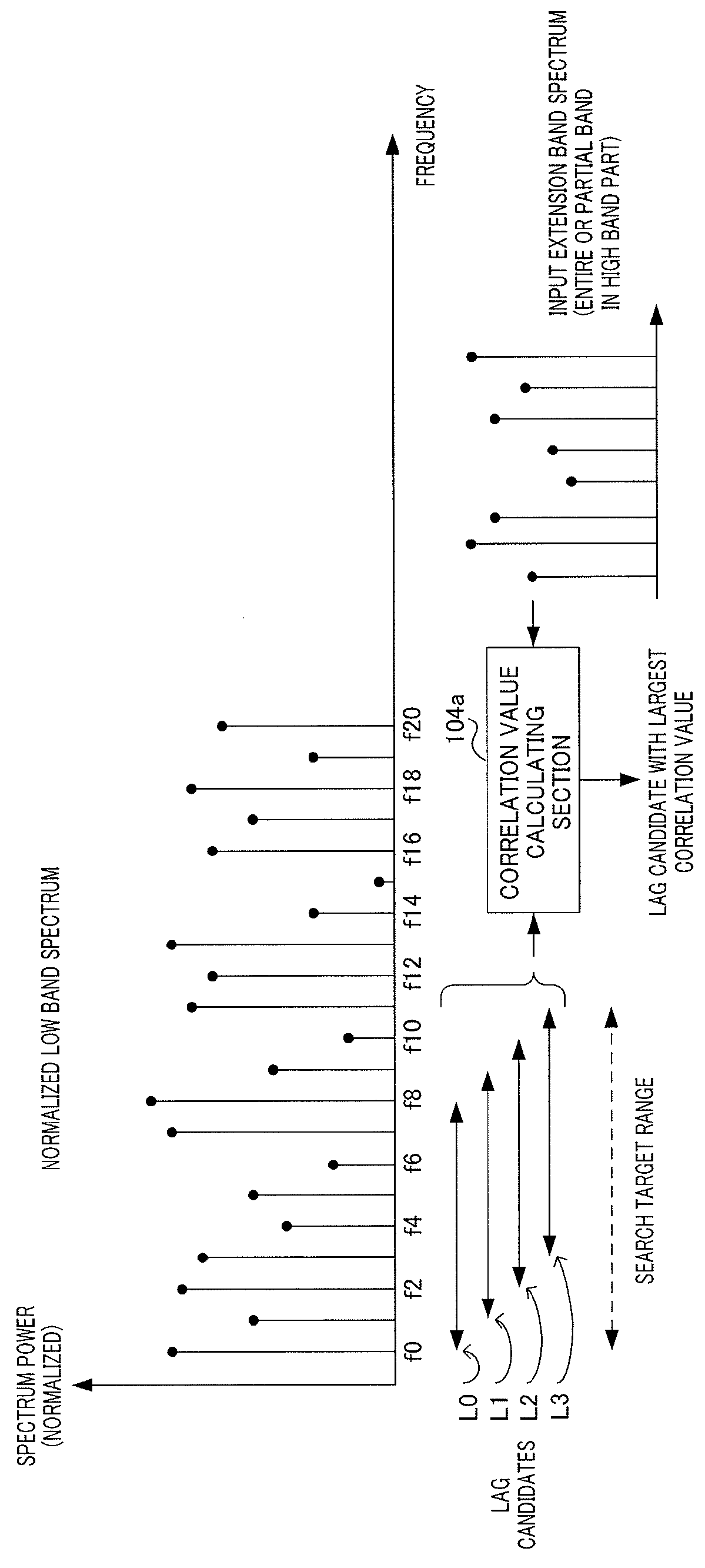
[0096]As described above, when encoding a spectrum in an extension band (high band part) of an input signal, a coding apparatus uses a spectrum resulting from a normalized low band spectrum being copied to the extension band as a spectrum fine structure. This can be regarded as utilizing a harmonic structure in a spectrum in a low band part of an input signal. In other words, provision of a clearer decoded signal can be expected by emphasizing the harmonic structure in the spectrum in the low band part of the input signal.

[0097]Therefore, in the present embodiment, a case where a harmonic structure in a normalized low band spectrum obtained in Embodiment 1 is emphasized further will be described.

[0098]FIG. 9 is a block diagram illustrating a configuration of coding apparatus 300 according to the present embodiment. In coding apparatus 300 illustrated in FIG. 9, components other than harmonic emphasizing section 301 are the same as those of coding apparatus 100 (FIG. 1) according to ...

embodiment 3

[0113]In Embodiment 3, the degree of emphasis of a harmonic structure in the harmonic emphasis processing in Embodiment 2 is adaptively controlled.

[0114]FIG. 12 is a block diagram illustrating a configuration of coding apparatus 500 according to the present embodiment. In coding apparatus 500 illustrated in FIG. 12, components other than sub-band amplitude normalizing section 501, threshold controlling section 502 and harmonic emphasizing section 503 are the same as those of coding apparatus 300 (FIG. 9) according to Embodiment 2, and thus are provided with reference numerals that are the same as those of coding apparatus 300, and a description thereof will be omitted here.

[0115]Sub-band amplitude normalizing section 501 outputs a normalized low band spectrum to threshold controlling section 502 and harmonic emphasizing section 503, and outputs a sub-band largest value in each sub-band, which corresponds to the output of largest value searching section 132 (FIG. 5), to threshold con...


PUM


Abstract

By copying to a high-frequency band portion (extension band) a low-frequency band portion in which peaking has been set to a sufficiently low state, this encoding device is capable of preventing generation of a spectrum with overly high peaking in the high-frequency band portion, and of generating a high-quality extension band spectrum. This device comprises: a maximum value search unit which searches, in each of multiple sub-bands obtained by dividing the low-frequency band portion of an audio signal and / or music signal below a prescribed frequency, for the maximum value of the amplitude of a first spectrum obtained by decoding first encoded data, which is encoded data in the low-frequency band portion; and an amplitude normalization unit which obtains a normalized spectrum by normalizing, at the maximum values of the amplitude of each sub-band, the first spectrum contained in each sub-band.

Description

TECHNICAL FIELD[0001]The present invention relates to a coding apparatus, a decoding apparatus, a coding method and a decoding method.BACKGROUND ART[0002]Patent Literature (hereinafter, referred to as “PTL”) 1 discloses a technique that enables efficient encoding of speech signals or music signals in a super-wide band (SWB) (typically, 0.05 to 14 kHz band). This technique has been standardized by ITU-T (see, for example, NPL1 and NPL2). In this technique, a low band part (a band of, for example, up to 7 kHz) of an input signal such as a speech signal or a music signal is encoded by a core coding section while a high band part (a band higher than, for example, 7 kHz) is encoded by an extension band coding section.[0003]In general, the core coding section uses CELP (code excited linear prediction) coding. Meanwhile, the extension band coding section performs encoding in the frequency domain using information encoded by the core coding section. More specifically, the extension band cod...

Claims


Application Information

Patent Timeline
Patent Type & Authority Patents(United States)
IPC IPC(8): G10L21/0388G10L19/26G10L19/02
CPCG10L19/265G10L21/0388G10L19/0204
Inventor KAWASHIMA, TAKUYADAIMOU, KATSUNORIOSHIKIRI, MASAHIRO
Owner PANASONIC INTELLECTUAL PROPERTY CORP OF AMERICA
Why Eureka
Try Eureka