Compact multi-port router device

a router and multi-port technology, applied in the direction of multiple-port networks, coupling devices, electrical devices, etc., can solve the problems of additional insertion loss, complex implementation of routing functions, so as to reduce the insertion loss, reduce the space requirement and mass, and improve the effect of electrical performan

Inactive Publication Date: 2016-07-12
CENT NAT DETUD SPATIALES (CNES) +3
View PDF4 Cites 0 Cited by
  • Summary
  • Abstract
  • Description
  • Claims
  • Application Information

AI Technical Summary

Benefits of technology

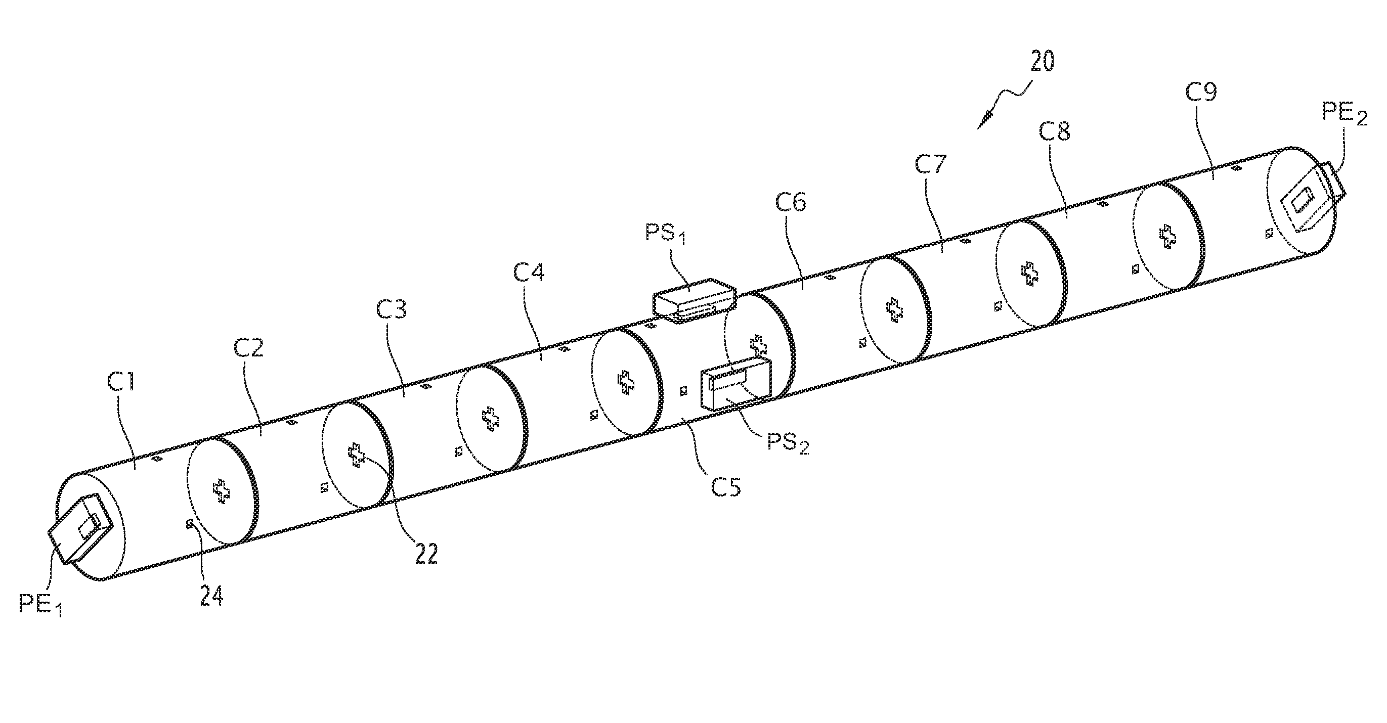
[0014]Advantageously, the multiport router device according to the invention is compact insofar as each input port and each output port is directly connected to at least one resonator, without connection elements such as waveguides or junctions. Thus, the invention makes it possible to obtain an advantage in terms of space requirement and mass as compared to existing solutions, and also to improve the electrical performance by limiting the insertion losses and eliminating the spiking recombination peaks that are typically due to the use of connection elements such as waveguides.

Problems solved by technology

The implementation of the routing functions is therefore much more complex than the implementation of the multiplexing functions.
Such a router device is cumbersome having a large mass and space requirement, as well as resulting in additional insertion loss.

Method used


Image

  • Compact multi-port router device
  • Compact multi-port router device
  • Compact multi-port router device

Examples


Embodiment Construction

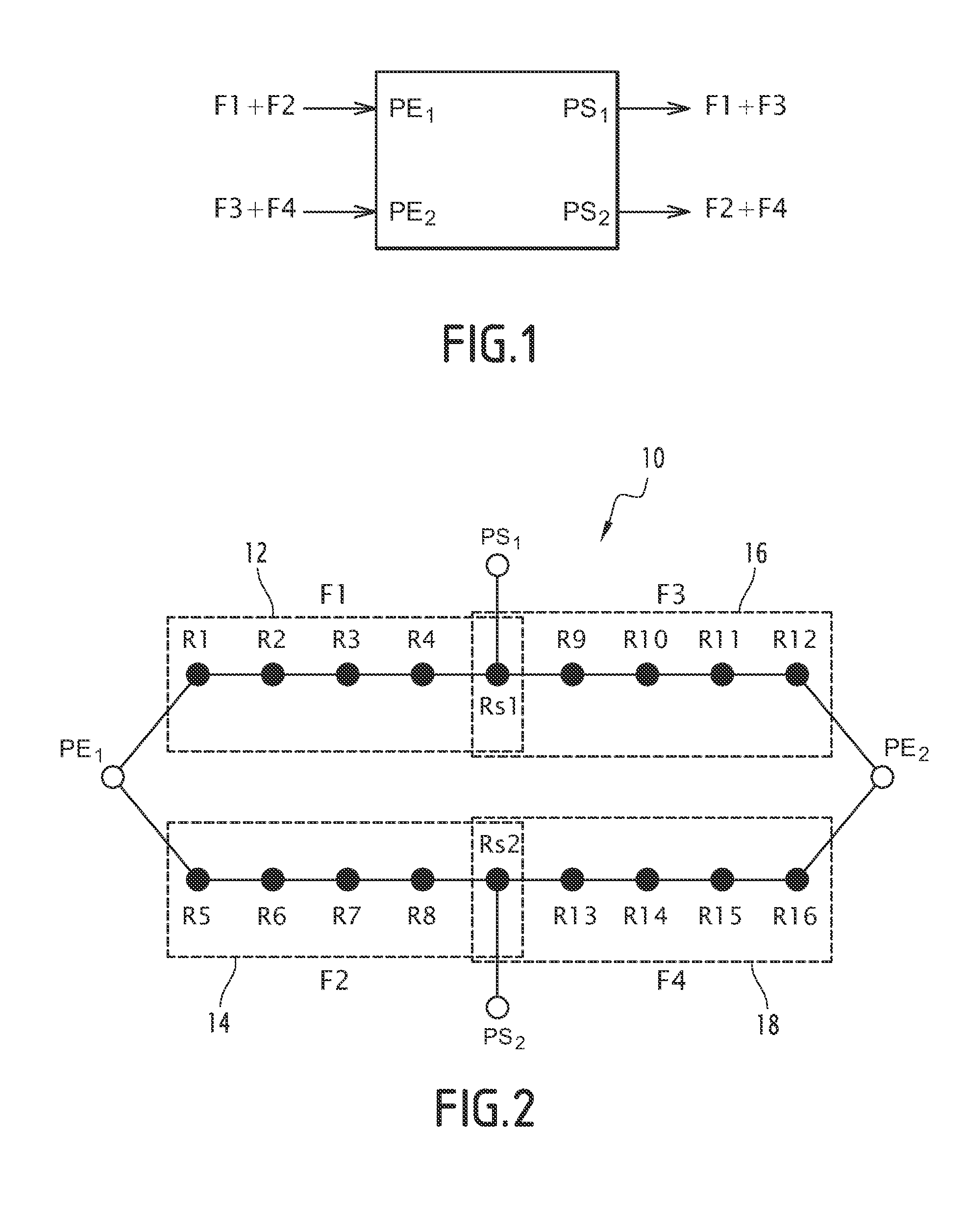
[0038]FIG. 1 illustrates in a functional manner a multi port router device having two input ports respectively denoted as PE1 and PE2 and two output ports respectively denoted as PS1 and PS2, capable of separating four frequency channels, each frequency channel having an associated carrier respectively denoted as F1, F2, F3 and F4.

[0039]In order to simplify the expression each frequency channel shall hereinafter be designated by the associated carrier or carriers.

[0040]A first input multiplex, forwarded on to the input port PE1, comprises two carrier frequency channels F1 and F2, and a second input multiplex, forwarded on to the input port PE2, comprises two carrier frequency channels F3 and F4. The channels are respectively separated and recombined. Thus, the frequency channel F1 of the first input multiplex is supplied over the first output multiplex on the output port PS1. The first output multiplex also includes the frequency channel F3 originating from the second input multiple...


PUM


Abstract

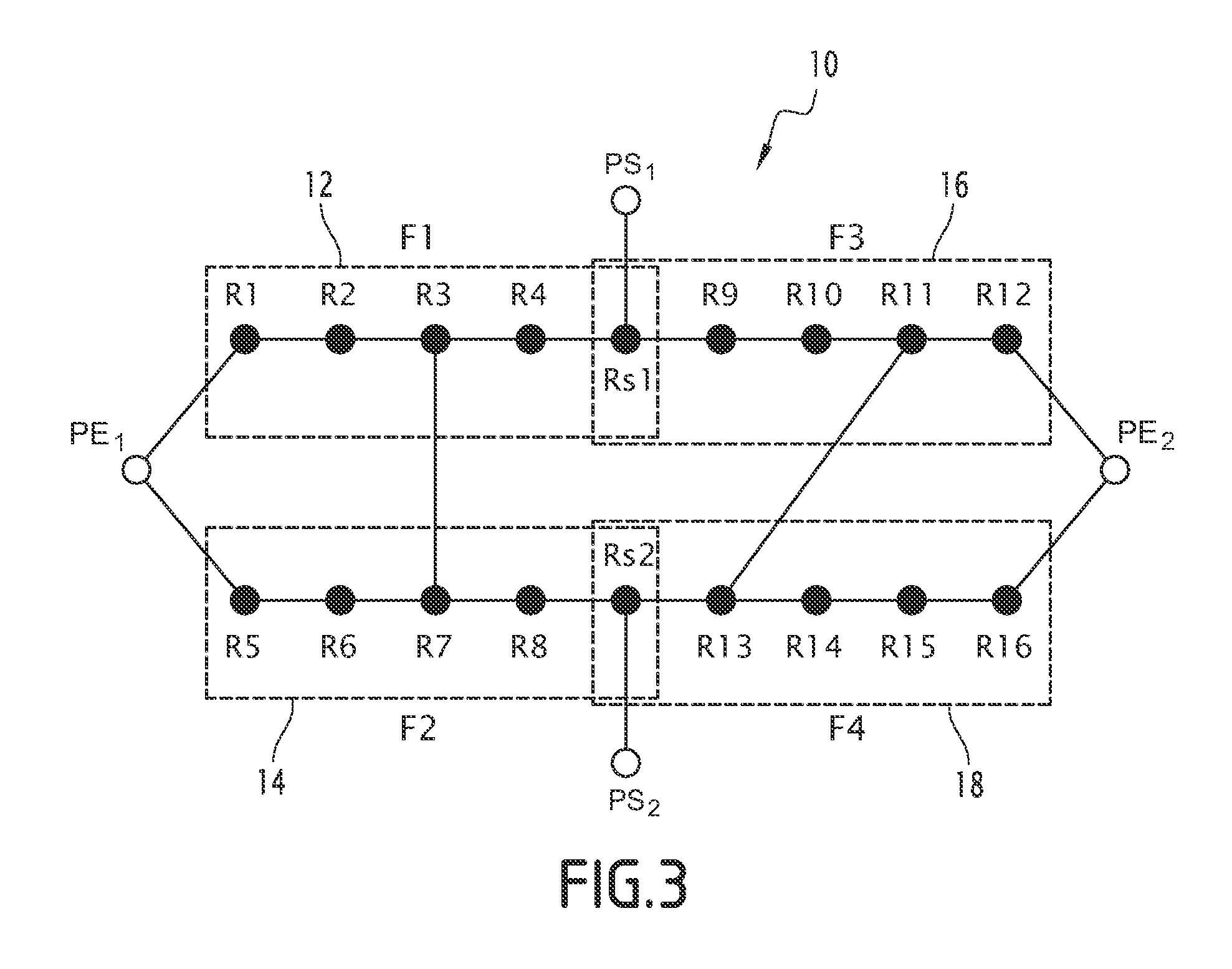
The invention relates to a multi port router device capable of carrying a number P, which is greater than or equal to three, of frequency channels, from a number M of input ports to a number N of output ports, at least one of the two numbers M and N being greater than or equal to two, characterized in that it includes at least two filters (12, 14, 16, 18), each filter comprising at least two coupled resonators, at least one resonator (Rs1, Rs2) being common to two different filters, and each input port and each output port being connected directly to at least one resonator. The router device is capable of appropriately performing routing in which it is possible to supply on at least one output port an output multiplex having at least a first and a second frequency channel, among which: the first frequency channel has originated from a first input multiplex, supplied on a first input port and comprising said first frequency channel, and at least one further frequency channel forwarded to a second output port of the device; and the second frequency channel is either forwarded from a second input port, or, when the first input multiplex comprises at least three different multiplexed frequency channels, the second frequency channel originates from the first input multiplex, the first second frequency channels, being frequentially disposed on both sides of a third frequency channel, with the said third frequency channel being routed to a different output port.

Description

RELATED APPLICATIONS[0001]This application claims the benefit of French Patent Application No. 12 59276 filed on Oct. 1, 2012. The entire disclosure of this application is incorporated herein by reference.FIELD OF THE INVENTION[0002]The present invention relates to a multi port router device capable of carrying a number P, which is greater than or equal to three, of frequency channels, from a number M of input ports to a number N of output ports.[0003]The invention pertains to the domain of hyperfrequency and microwave communications, and finds particular application in the field of telecommunication satellites.BACKGROUND OF THE INVENTION[0004]The state of the art includes various known technologies including various architectures for devices that are capable of performing hyperfrequency communications functions, in particular functions such as filtering, multiplexing and routing of hyperfrequency microwave signals transmitted by frequency channels each one thereof having an associa...

Claims


Application Information

Patent Timeline
Patent Type & Authority Patents(United States)
IPC IPC(8): H01P5/12H01P1/208H03H7/46H01P1/213
CPCH03H7/46H01P1/2086H01P1/2133H01P5/12
Inventor BILA, STEPHANEESTAGERIE, LETITIAPACAUD, DAMIENPUECH, JEROMESEYFERT, FABIENVERDEYME, SERGEEZZEDDINE, HUSSEINMAZET, PIERRE
Owner CENT NAT DETUD SPATIALES (CNES)
Why Eureka
Try Eureka