Ankle support

a technology for supporting the ankles and supporting the knees, which is applied in the field of ankle braces, can solve the problems of inability to permanently set the precise degree of pronation or supination, the connection is therefore inconvenient to guide, and the connection at both ends of the fixing belt has proved to be disadvantageous, so as to facilitate the guide of the compression belt

Active Publication Date: 2016-07-19
BSN MEDICAL GMBH & CO KG
View PDF12 Cites 4 Cited by
  • Summary
  • Abstract
  • Description
  • Claims
  • Application Information

AI Technical Summary

Benefits of technology

[0021]In a preferred embodiment, one end is fixedly connected to the main body. This allows a precise degree of pronation to be set. In addition, it makes it easier for the user to put on the fixing belt.
[0038]In addition, it is particularly preferable when the compression belt is affixed to the sole section. Such a fixation of the compression belt preferably in the area of the heel of a foot surrounded by the main body makes it easier to guide the compression belt when putting on the ankle brace, and a reproducible location for guidance is ensured in the area of the sole section.

Problems solved by technology

It is impossible to permanently set a precise degree of pronation or supination when the end of the fixing belt opposite the end at which initial tension is introduced is connected to the main body in a yielding manner and not fixedly, and the connection is therefore unable to withstand constant opposing force.
Such a connection at both ends of the fixing belt has therefore proven to be disadvantageous.
Furthermore, the fixing belt cannot be completely released from the main body, which can cause unnecessary difficulty or effort for the user the next time the ankle brace is put on.
The fact that the fixing belt is permanently attached to the sole section of the main body is disadvantageous in that the fixing belt cannot be moved freely along the sole section to search for an individual optimum position.
In addition, the fact that the fixing belt is permanently connected to the sole section causes the main body to twist or shift relative to the foot surrounded by the main body when the initial tension applied to the first and second end is not equivalent.
Pronation or supination cannot be effectively adjusted.
In addition, the user must adjust the initial tension at two ends of the fixing belt and adjust them in relation to each other, if necessary, which makes putting on the ankle brace complicated.
From all of the above, it is clear that the brace according to U.S. 2007 / 0049857 can immobilize the foot joint but cannot correct the position of the bones relative to each other.
The position of the bones in the area of the ankle also cannot be corrected with this brace; the ankle can also only be immobilized.

Method used


Image

  • Ankle support
  • Ankle support
  • Ankle support

Examples


Embodiment Construction

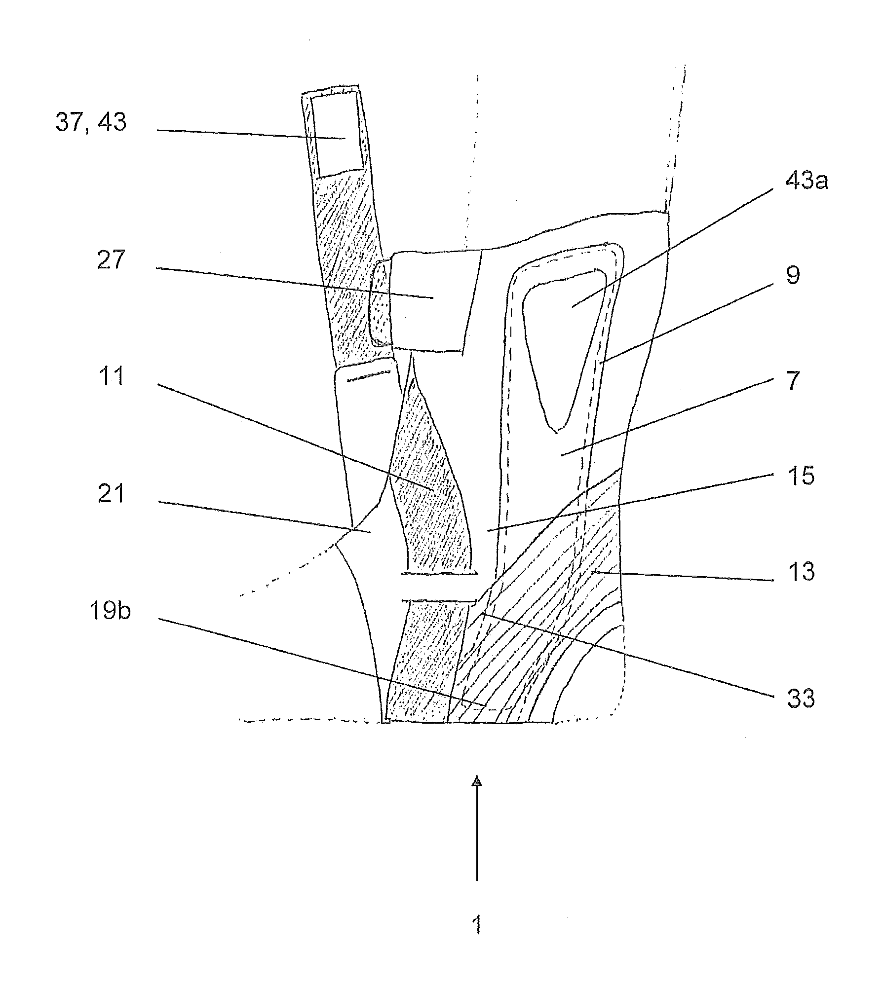
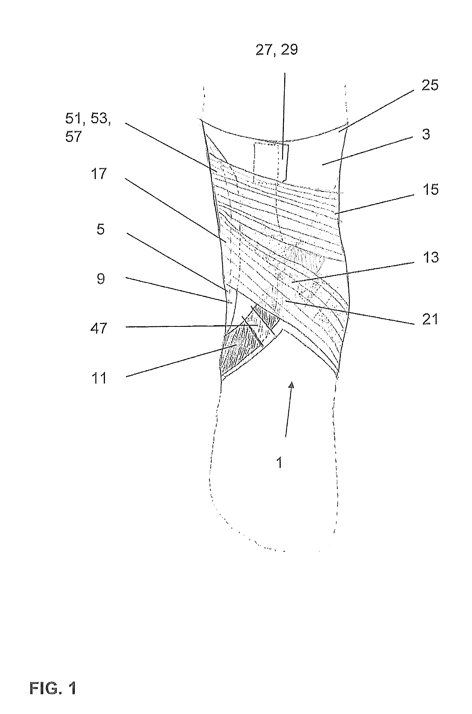
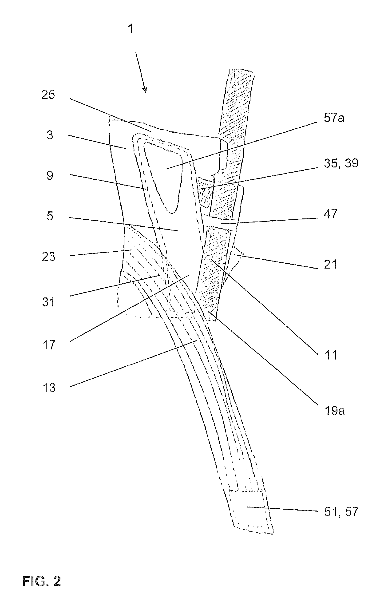
[0047]FIG. 1 shows an exemplary embodiment of an ankle brace 1 according to the invention that can be used in the present case to adjust the pronation of an ankle that it surrounds. The ankle brace 1 comprises a main body 3, a lateral and medial splint element 5, 7, an applied reinforcement 9, a fixing belt 11, and a compression belt 13.

[0048]The main body 3 is formed from a flexible material to surround, i.e., closely lie against a human leg in the area of the ankle joint from the lower leg to the midfoot. The main body 3 has a medial section 15 (see FIG. 3), a lateral section 17 (see FIG. 2), a sole section 19 (see FIG. 5) with a lateral and medial side 19a, 19b, an arch and instep section 21 (see FIGS. 1 and 6), and a posterior section 23 (see FIG. 4). The sections can be formed together as a single piece, or the main body 3 can have sections that are, for example, sewn together.

[0049]The medial section 15 is provided to contact the medial side, the lateral section 17 is provided...


PUM


Abstract

An ankle brace having a flexible main body that is designed to surround a human leg from the ankle from the lower leg to the midfoot, and having a fixing belt that can be wound around the main body that is affixed, with the first end, to the lateral section of the main body adjacent to its top end, and, with the second end, to the medial section of the main body adjacent to its top end. The ankle brace makes it possible to easily adjust a certain degree of pronation and at the same time be comfortable to wear. One of the first and second end is fixedly or releasably connected to the main body in a fixed position relative to the main body, and that the other of the first and second end is releasably connected to the main body.

Description

TECHNICAL FIELD AND BACKGROUND OF THE INVENTION[0001]The present invention relates to an ankle brace comprising a flexible main body that is designed to surround a human leg in the area of the ankle from the lower leg to the midfoot, wherein the main body comprises a medial section, a lateral section, a sole section having a lateral and medial side, and an arch and instep section, wherein the medial section is provided to contact the medial side, the lateral section is provided to contact the lateral side, the sole section is provided to contact the sole, and the arch and instep section is provided to contact the arch and / or instep of the foot, and having a fixing belt that can be wound around the main body, which has a first end and a second end, wherein the first end of the fixing belt is connected to the lateral section of the main body, and the second end is connected to the medial section of the main body adjacent its top end, and wherein the fixing belt is movably guided aroun...

Claims


Application Information

Patent Timeline
Patent Type & Authority Patents(United States)
IPC IPC(8): A61F5/01A61F13/06
CPCA61F5/0111A61F5/0104A61F13/066
Inventor GRUNDEN, JENNIFERSCHEIB, BIRGIT
Owner BSN MEDICAL GMBH & CO KG
Why Eureka
Try Eureka