Clip for tensioning and attaching trim cover, and vehicle seat

a technology for attaching trim covers and clips, which is applied in the direction of snap fasteners, buckles, chairs, etc., can solve the problems of production efficiency drop, achieve easy and precise alignment, facilitate production efficiency improvement, and improve the commodity value of the entire seat

Inactive Publication Date: 2011-03-08
TS TECH CO LTD
View PDF9 Cites 61 Cited by
  • Summary
  • Abstract
  • Description
  • Claims
  • Application Information

AI Technical Summary

Benefits of technology

[0007]It is, therefore, desirable to provide a clip which is hard to be considerably shifted relative to a longitudinal bulged member of a tensioning cord attached to a portion of a trim cover for a seat and facilitates improving of the production efficiency. Moreover, there is a need for a clip which, in a condition where the clip is attached through a longitudinal bulged member to a portion of a trim cover for a seat, can be easily and precisely aligned with an exposed axial portion of an insert wire embedded in a cushioned pad for the seat, thus facilitating improving of the commodity value for the entire seat.
[0009]The clip constructed as discussed above includes the stopper piece which is adapted to be inserted through the through-hole of the tensioning cord, so that even if the trim cover having the clip attached to the longitudinal bulged member thereof, or the clip attached to the portion of the trim cover through the longitudinal bulged member is subjected to vibration, shock, etc. during conveying of the trim cover toward a production line in which the trim cover is tensioned and attached at the portion thereof to the cushioned pad by the clip and the cushioned pad is then covered by the trim cover, and / or during treating of the trim cover in the production line, the clip is prevented from being considerably shifted relative to the longitudinal bulged member. Therefore, frequencies of correcting a position of the clip with respect to the longitudinal bulged member and time taken in order to correct the position of the clip can be reduced. Thus, the clip according to the embodiment of the present invention contributes to decreasing of process tact. Moreover, the time taken in order to correct the position of the clip can be reduced, thus allowing a worker to be devoted to the assembling of the cushion, without being imposed with an additional burden, so that production efficiency can be improved. In addition, the clip is hard to be shifted with respect to the longitudinal bulged member, thus facilitating improving of the commodity value of the entire seat.
[0011]In the case where the stopper piece has the width which is less than the width of the frame body and less than length of the laterally elongated through-hole, even if the hook portion of the clip is positionally shifted with respect to the exposed axial portion of the wire, the positional deviation of the hook portion relative to the exposed axial portion of the wire can be adjusted in such a manner that the hook portion is aligned with the exposed axial portion of the wire, by causing the frame body to be shifted relative to the longitudinal bulged member in such a manner that the stopper piece is allowed to be shifted within the through-hole. Therefore, the clip can be appropriately hooked through the hook portion to the exposed axial portion of the wire and facilitates the tensioning of the trim cover and stable attaching of the portion of the trim cover to the cushioned pad, thus improving the commodity value for the entire seat.
[0013]In the case where the clip includes the elastic guide portion for guiding the exposed axial portion of the wire toward the innermost region of the substantially C-shaped hook portion, the exposed axial portion of the wire can be easily guided into the innermost region of the substantially C-shaped hook portion.

Problems solved by technology

Therefore, in the production line, prior to the hooking of the hook portions of the clips to the exposed axial portions of the insert wire, the positional deviation of the clips relative to the longitudinal bulged member must be corrected, thus causing drop of the production efficiency.

Method used


Image

  • Clip for tensioning and attaching trim cover, and vehicle seat
  • Clip for tensioning and attaching trim cover, and vehicle seat
  • Clip for tensioning and attaching trim cover, and vehicle seat

Examples


Embodiment Construction

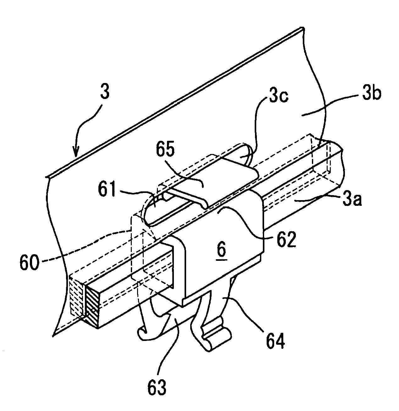
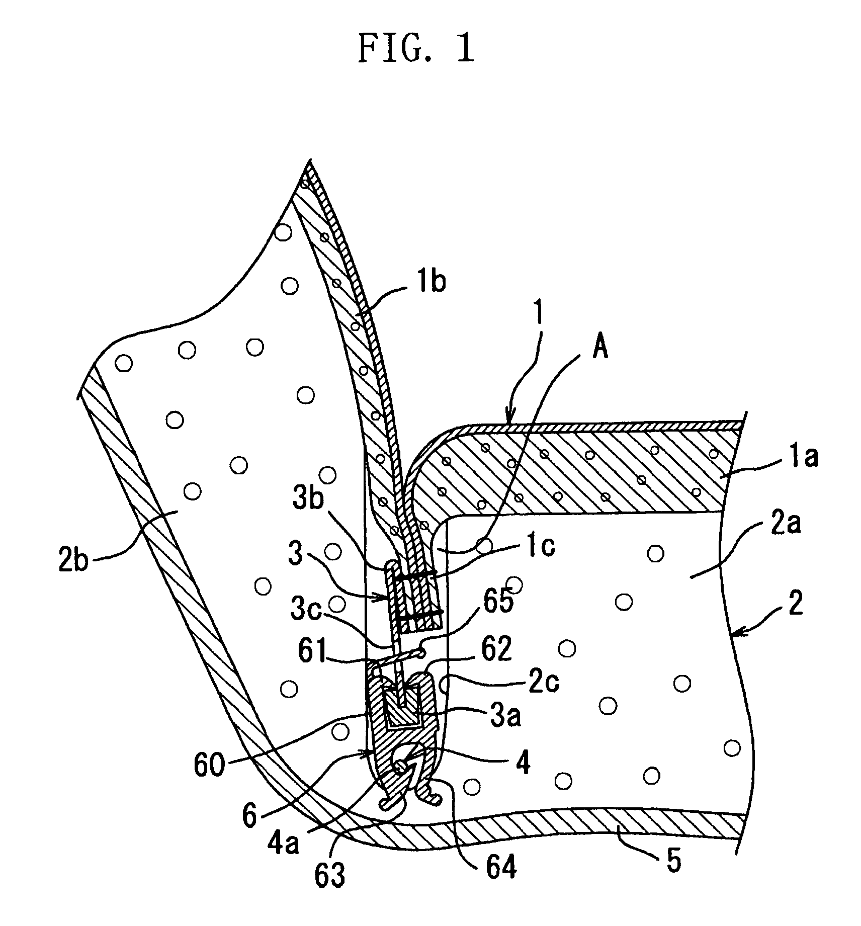
[0020]Referring to FIG. 1, there is illustrated a tensioning structure which allows a trim cover 1 for a seat cushion of a vehicle seat to be tensioned and attached at a portion 1c thereof to a cushioned pad 2 for the seat cushion by clips 6 according to an embodiment of the present invention in order to assemble the seat cushion of the vehicle seat (only one clip 6 is shown in FIG. 1). The trim cover 1 includes a first cover portion 1a covering a first portion 2a of the cushioned pad 2 which positionally corresponds to a section of the seat cushion on which a person is to sit, a second cover portion 1b covering a second bulged portion 2b of the cushioned pad 2 which positionally corresponds to a bank section of the seat cushion, and the third portion 1c formed by causing a terminal region of the first cover portion 1a and a terminal region of the second cover portion 1b to be sewed together. The third portion 1c of the trim cover 1 is received in a recess portion A of the cushioned...


PUM


Abstract

A clip for use in a cushion for a vehicle seat, wherein the cushion includes a cushioned pad and a trim cover , the cushioned pad having a recess portion and a wire embedded in the cushioned pad so as to be partially exposed to the recess portion from the cushioned pad, the trim cover having a portion, a longitudinal tensioning cord attached to the portion of the trim cover, a longitudinal bulged member provided along a longitudinal edge portion of the cord, and a laterally elongated through-hole formed in the cord. The clip which includes pawls, a stopper piece and a hook portion is adapted to be hooked between the bulged member and an exposed axial portion of the wire with the frame body receiving the bulged member therein and retainingly holding the bulged member, with the pawls being stoppingly engaged with the bulged member, with the stopper piece being inserted through the through-hole, and with the hook portion being hooked to the exposed axial portion of the wire, whereby the trim cover is tensioned and attached at the portion thereof to the cushioned pad by the clip.

Description

BACKGROUND OF THE INVENTION[0001]1. Field of the Invention[0002]The present invention relates to a clip for tensioning a trim cover for covering a cushioned pad for a seat, and attaching a portion of the trim cover to the cushioned pad, by utilizing a tensioning cord attached to the portion of the trim cover. The present invention also relates to a vehicle seat in which a trim cover for the vehicle seat is tensioned and attached at a portion thereof to a cushioned pad for the vehicle seat by clips.[0003]2. Description of the Related Art[0004]As a clip for tensioning a trim cover for a vehicle seat and attaching a portion of the trim cover to a cushioned pad for the vehicle seat, there is proposed a clip that includes a frame body formed substantially into an upward facing U-shape in cross-section, a pair of spaced apart inverted-pawls provided at edges of both ends of the frame body so as to inwardly face each other, and a hook portion provided at the frame body so as to extend down...

Claims


Application Information

Patent Timeline
Patent Type & Authority Patents(United States)
IPC IPC(8): A47C27/00B60N2/90
CPCB60N2/5825Y10T24/44
Inventor MASHIMO, TOMOYUKI
Owner TS TECH CO LTD
Why Eureka
Try Eureka