Device for separating water from sludge

a technology for separating devices and sludge, which is applied in the direction of separation processes, filtration separation, feed/discharge of settling tanks, etc. it can solve the problems of inconvenient transportation and the failure of separation devices to achieve this goal, and achieve the effect of convenient guiding of sludge and water, convenient post-processing, and cheaper and more efficien

Inactive Publication Date: 2018-08-21
ZHU ZIYU
View PDF4 Cites 63 Cited by
  • Summary
  • Abstract
  • Description
  • Claims
  • Application Information

AI Technical Summary

Benefits of technology

[0014]Through the feeding mechanism of the present invention, the sludge pipeline can be conveniently inserted into the watercourse, thereby easily guiding the sludge and the water into the feeding hopper. Thus, the sludge in the watercourse can be effectively processed, avoiding the manual retrieval of sludge out of the watercourse, which is cheaper and more efficient. Additionally, the sludge and the impurities (e.g., tree branches) entered into the feeding hopper can be thoroughly crushed by the two crushing wheels, greatly facilitating the post-processing. The sludge and the water can be effectively separated into the sludge cavity and the purification cavity, achieving an ideal separation effect. Furthermore, the spiral blades in the feeding cylinder can help transfer the sludge. During the rotating process of the spiral blades, the sludge and the water can be further separated. Under the action of the heating pipe, the water in the sludge can evaporate faster, and the dried sludge can be easily processed. Through the interaction between the hydraulic cylinder and the hydraulic rod, the sludge can be conveniently squeezed by the squeezing plate and cut by the cutting blades. The block-shaped sludge can be conveniently processed. Moreover, the electric telescopic rod and the push plate allow the sludge blocks to be pushed out from the discharge pipe. Furthermore, the filter screen disposed in the purification cavity can be easily replaced, enabling the impurities in the water to be thoroughly filtered. Thus, the water quality can be significantly improved. The exhaust fan can accelerate the air circulation in the sludge cavity so that the water loss speed can be higher.

Problems solved by technology

As sludge is mostly water with a lesser amount of solid material, it is very inconvenient to transport due to its predominately liquefied state.
However, these traditional separation devices fail to achieve this goal due to their unreasonable structures.

Method used


Image

  • Device for separating water from sludge
  • Device for separating water from sludge
  • Device for separating water from sludge

Examples


Embodiment Construction

[0021]Drawings and detailed embodiments are combined hereinafter to elaborate the technical principles of the present invention.

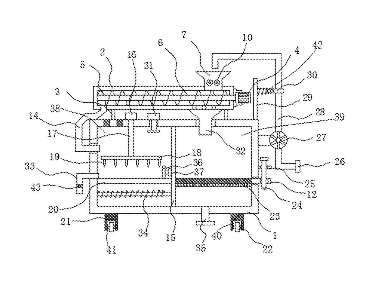
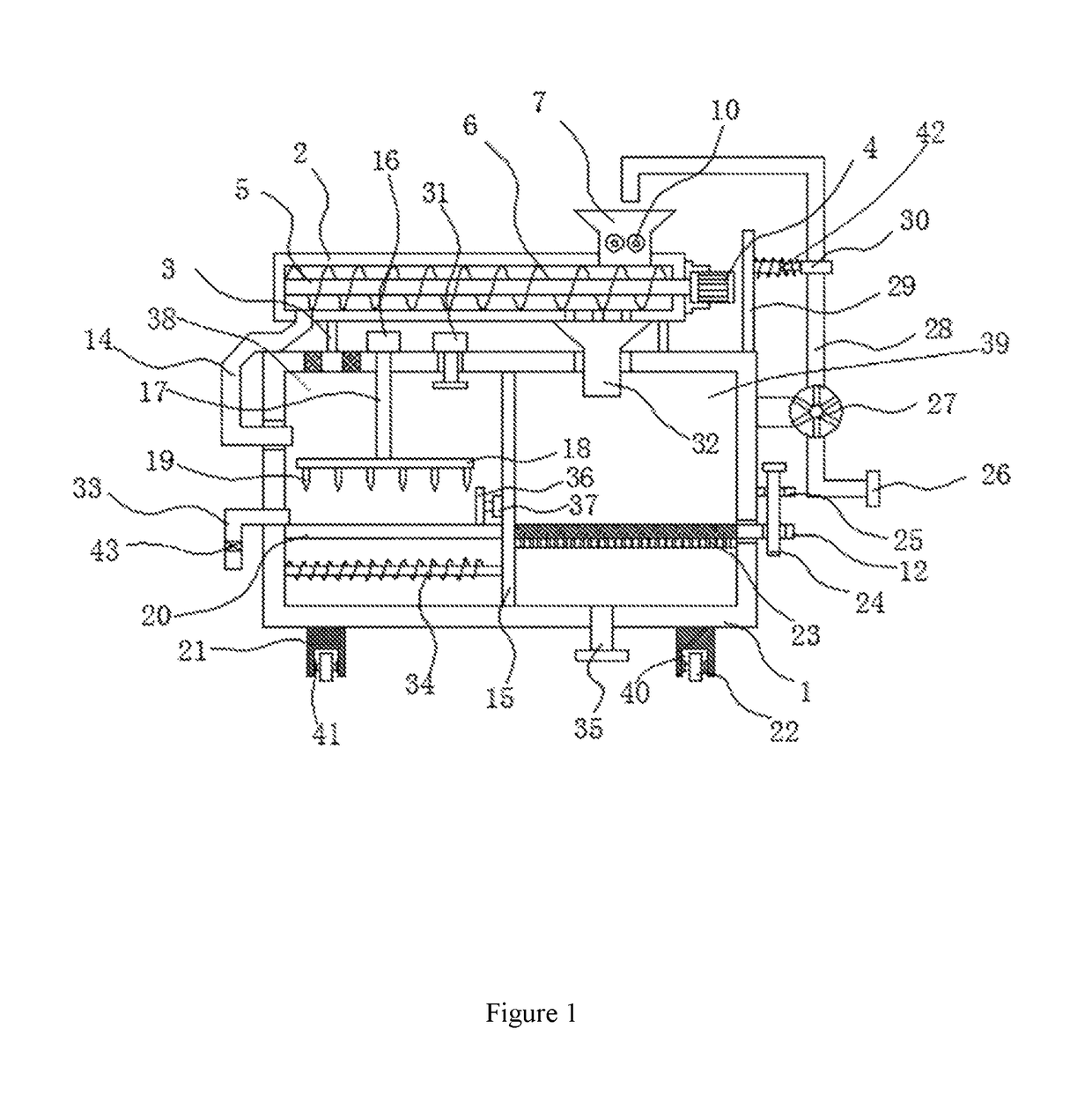
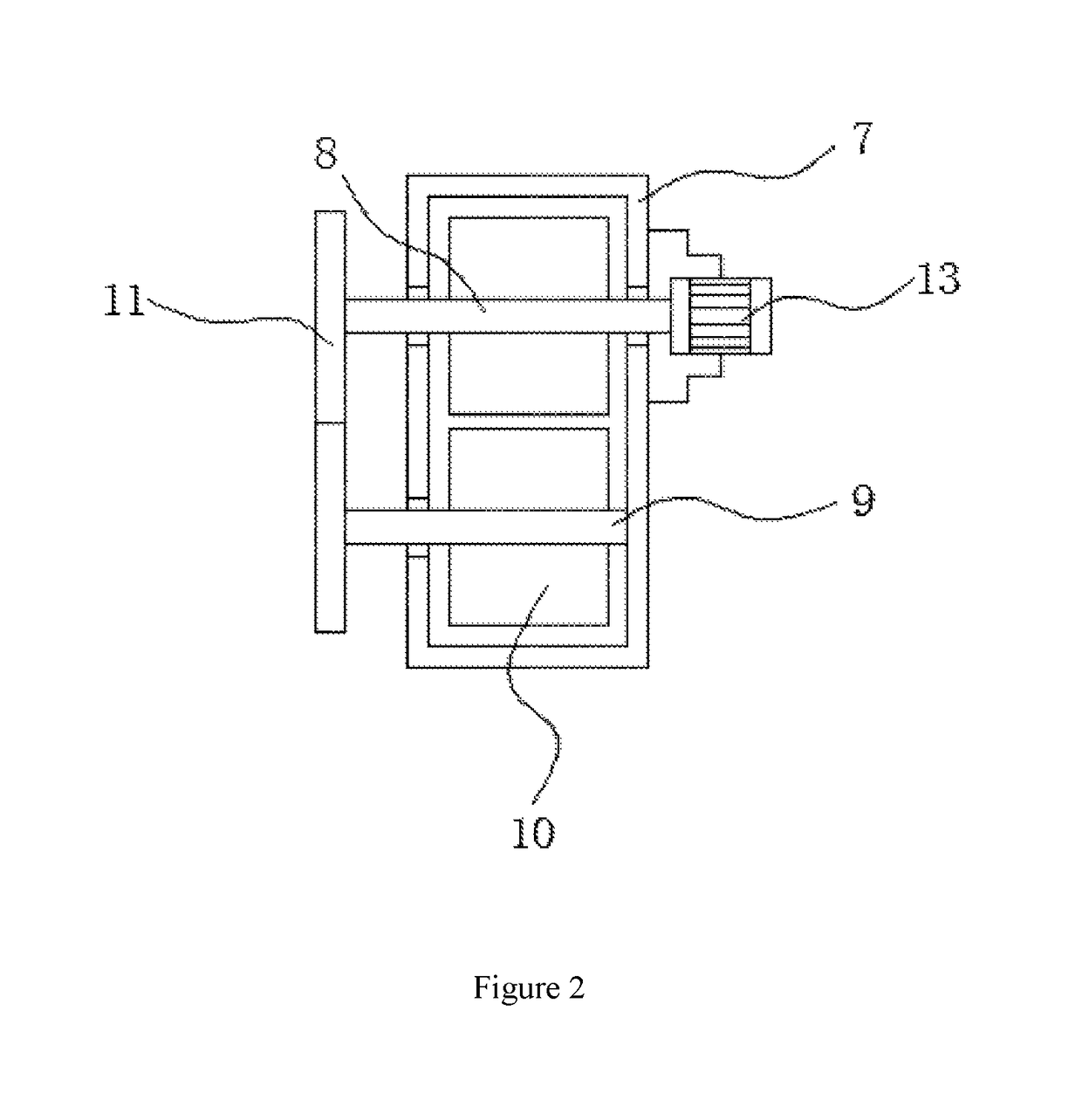
[0022]As shown in FIGS. 1-3, a device for separating the water from the sludge comprises a processing box 1, wherein an exhaust fan 31 is fixedly connected to the top of the processing box 1, and the input end of the exhaust fan 31 penetrates through the top of the processing box 1, and extends to the interior of a sludge cavity 38. A heat dissipation hole corresponding to the exhaust fan 31 is formed in the top of the sludge cavity 38. According to the exhaust fan 31, the air circulation in the sludge cavity 38 can be accelerated, making the water loss speed of the sludge become higher. A feeding cylinder 2 is disposed above the processing box 1, and the feeding cylinder 2 is fixedly connected to the processing box 1 through a plurality of connecting rods 3. A rotating rod 5 is rotationally connected into the feeding cylinder 2. A first rotating motor 4 is...


PUM

PropertyMeasurementUnit
heataaaaaaaaaa
water loss speedaaaaaaaaaa
structureaaaaaaaaaa

Abstract

A device for separating water from sludge comprising a processing box, wherein a feeding cylinder is disposed above the processing box, and the feeding cylinder is fixedly connected to the processing box through a plurality of connecting rods; a rotating rod is rotationally connected into the feeding cylinder; a first rotating motor is fixedly connected to one side of the feeding cylinder; the output end of the first rotating motor penetrates through the side wall of the feeding cylinder, and is fixedly connected to the rotating rod; a spiral blade is fixedly sleeved with the rotating rod, and the outer side of the spiral blade is matched with the inner side wall of the feeding cylinder.

Description

TECHNICAL FIELD OF THE INVENTION[0001]The present invention relates to the technical field of sludge processing, and more particularly, to a device for separating water from sludge.BACKGROUND OF THE INVENTION[0002]During the construction of a city watercourse, a large amount of sludge needs to be processed before being transported away and used for other purposes. As sludge is mostly water with a lesser amount of solid material, it is very inconvenient to transport due to its predominately liquefied state. In order to achieve an effective separation between the water and the sludge, various separation devices are in the market. However, these traditional separation devices fail to achieve this goal due to their unreasonable structures. Thus, it's urgent for those skilled in this field to develop a novel device capable of effectively separating water from sludge.SUMMARY OF THE INVENTION[0003]The purpose of the present invention is to solve the shortcomings (e.g., failing to achieving...

Claims


Application Information

Patent Timeline
Patent Type & Authority Patents(United States)
IPC IPC(8): C02F11/12B01D21/24C02F11/16C02F11/121C02F11/125C02F11/13
CPCC02F11/00C02F11/121C02F2103/007C02F2303/26C02F11/125C02F11/13C05F7/00B01D29/03Y02A40/20C05F17/50
Inventor ZHU, ZIYU
Owner ZHU ZIYU
Why Eureka
Try Eureka