Catheter

a catheter and diagnostic technology, applied in the field of catheters, can solve the problems of lowering the operationality of the catheter, difficult for the operator to transmit the force of pushing the catheter to the distal end of the catheter, and the inability to insert the catheter into the organism by operating the guide wir

Active Publication Date: 2005-11-22
TERUMO KK
View PDF13 Cites 67 Cited by
  • Summary
  • Abstract
  • Description
  • Claims
  • Application Information

AI Technical Summary

Benefits of technology

[0027]According to this constitution, since the imaging core is covered with the protective tube, the image cor

Problems solved by technology

If the guide wire does not project to the exterior beyond the whole length of the catheter, the guide wire terminates at an intermediate position in the catheter, so that it is impossible to insert the catheter into an organism by operating the guide wire.
Where the guide wire projects to the exterior beyond the whole length of the catheter, the guide wire projecting to the exterior is too long, resulting in

Method used


Image

  • Catheter
  • Catheter
  • Catheter

Examples


first embodiment

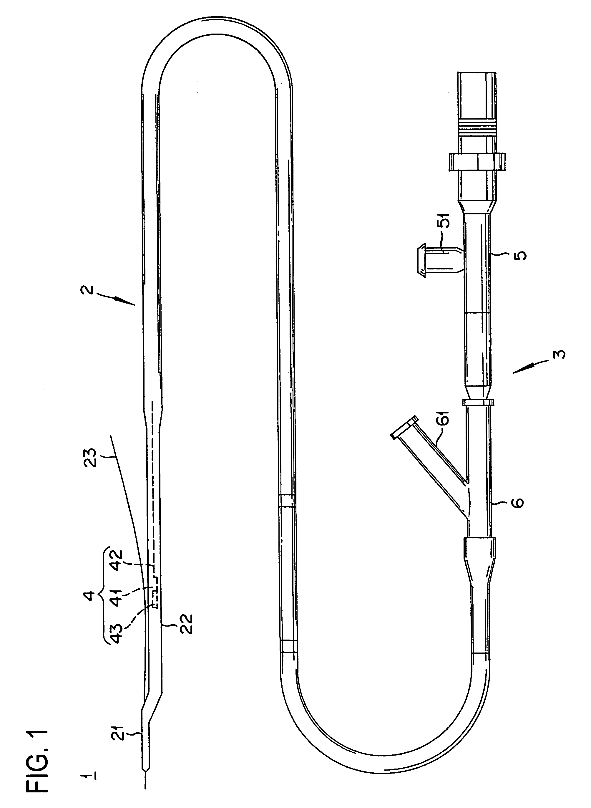
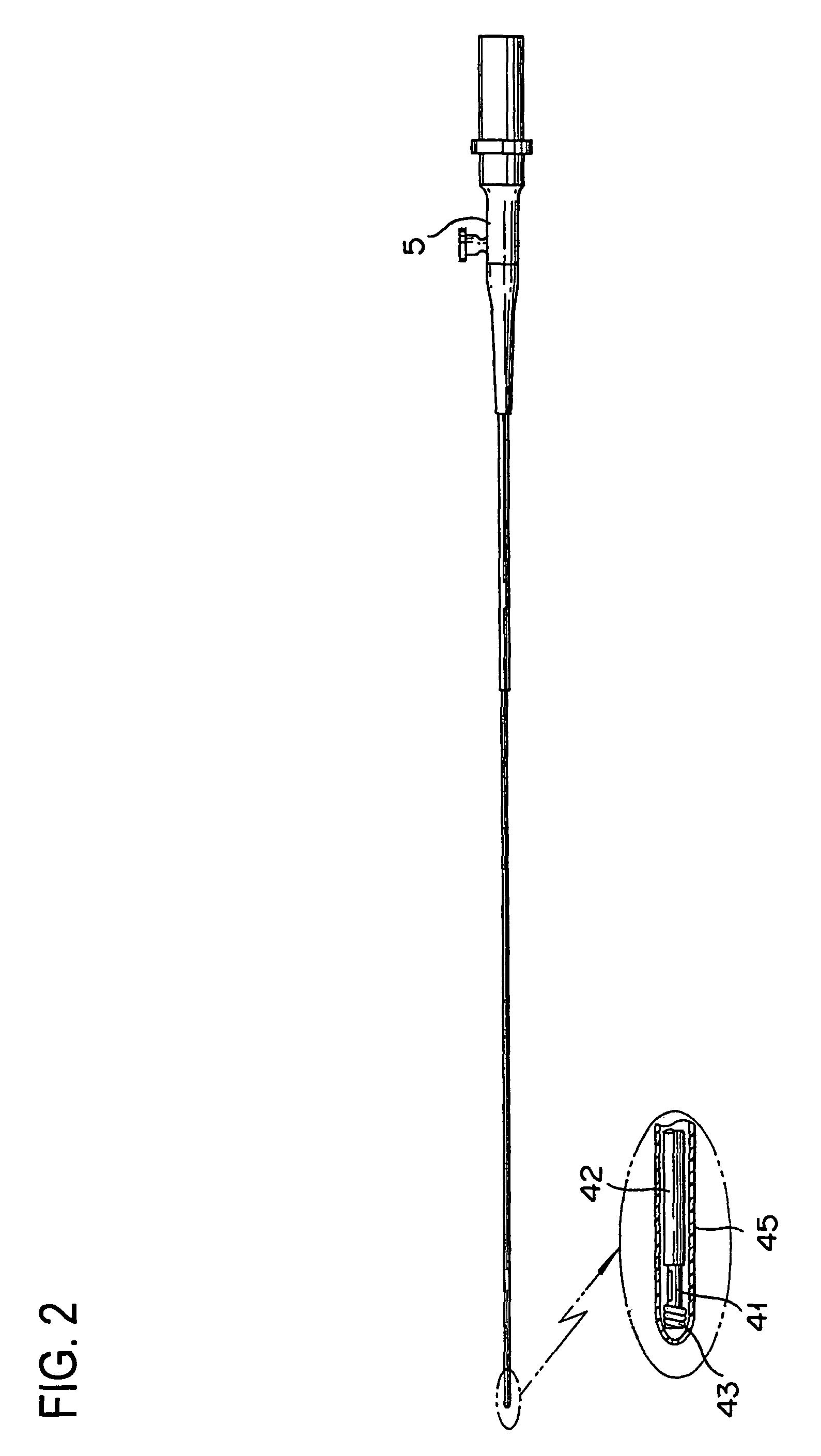
[0037]FIG. 1 illustrates an ultrasound catheter to which the present invention is applied, and FIG. 2 illustrates an imaging core and a connector.

[0038]The ultrasound catheter 1 shown in FIG. 1 is composed of a sheath 2 and an operating unit 3. The sheath 2 is inserted into a body cavity, and the operating unit 3 is not inserted into the body cavity but is disposed on the side of the hand or fingers of the user for operation by the user.

[0039]The sheath 2 includes a sheath distal end portion 21 and a sheath main body portion 22. The sheath distal end portion 21 is provided on a lateral side of a distal end portion of the sheath main body portion 22 so as to have an axis different and deflected from the center axis of the sheath main body portion 22. The sheath distal end portion 21 is provided with a straight lumen (second guide wire lumen) through which a guide wire 23 can be passed, in the same manner as a conventional RX type catheter.

[0040]In addition, the sheath main body porti...

second embodiment

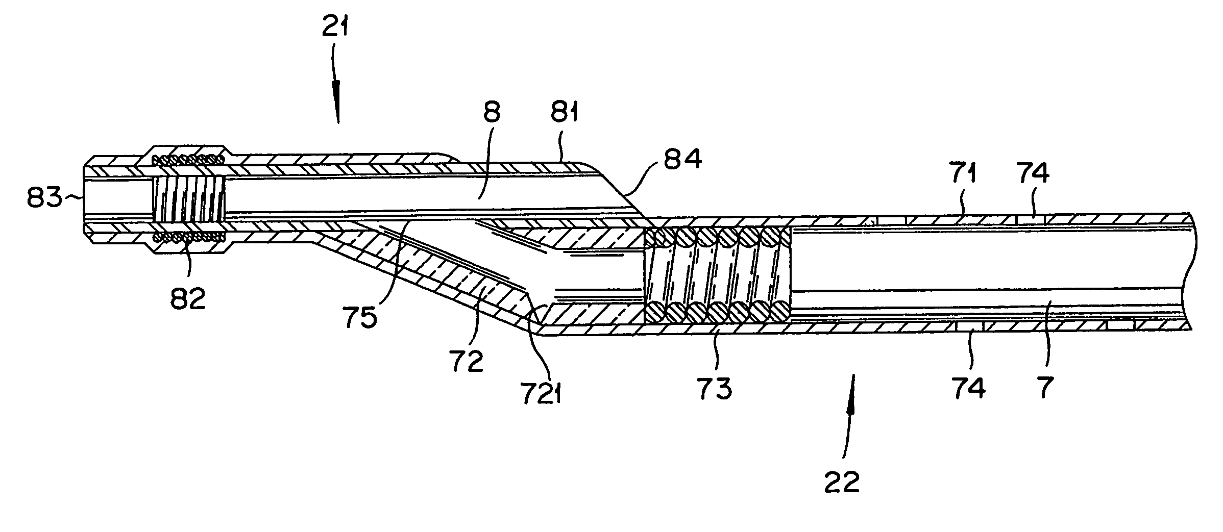
[0082]Next, a case where the above-described ultrasound catheter 1 is partly improved will be described. The ultrasound catheter 1 in this second embodiment is different from the first embodiment in that the first lumen 7 provided in the sheath main body portion 22 is not communicated with the second lumen 8 provided in the sheath distal end portion 21 but opened to the exterior of the sheath main body portion 22, namely, toward an organism.

[0083]FIG. 5 is a sectional view showing the constitution of the sheath distal end portion and the sheath main body portion according to the second embodiment. Since the ultrasound catheter 1 in the second embodiment is nearly the same with the ultrasound catheter 1 in the first embodiment, the same components as those in the first embodiment are denoted by the same reference numerals as used above, and description thereof is omitted.

[0084]In the second embodiment, a reinforcing part 76 is attached to the catheter tube 71. The reinforcing part 76...


PUM


Abstract

A catheter includes a sheath main body portion, a first lumen, a sheath distal end portion, and a second lumen. The sheath main body portion is inserted into an organism. The first lumen is a passage provided in the sheath main body portion and through which a guide wire for guiding the sheath main body portion in an organism can be passed. The sheath distal end portion is provided on a lateral side of a distal end portion of the sheath main body portion. The second lumen is a passage different from the first lumen, provided in the sheath distal end portion, and through which a guide wire can be passed. The catheter can have both ease of exchange of catheter, which is the merit of an RX type catheter, and distal end pushing force transmission performance (pushability), which is the merit of an OTW type catheter.

Description

BACKGROUND OF THE INVENTION[0001]The present invention relates to a diagnostic catheter used for various kinds of diagnosis in the state of being inserted in a body cavity or lumen such as a blood vessel, a vas, and a digestive organ, and particularly to a rapid-exchange (RX) type catheter provided at its distal end with a lumen for insertion of a guide wire.[0002]In a blood vessel insertion lumen represented by a catheter for use in Percutaneous Transluminal Coronary Angioplasty (PTCA) (this catheter will hereinafter be referred to as PTCA catheter), a guide wire lumen for insertion of a guide wire is provided over the whole length of the catheter in addition to a working lumen used for treatment or diagnosis.[0003]The guide wire is inserted into the guide wire lumen prior to the insertion of the catheter into a blood vessel, and its distalcend precedes in the blood vessel to guide the distal end of the catheter to the vicinity of the diseased part (angiostenosis portion).[0004]The...

Claims


Application Information

Patent Timeline
IPC IPC(8): A61B8/12A61M25/00
CPCA61B8/12A61B8/4461A61M25/0068A61M25/0052A61M25/007A61M2025/1056
Inventor OOKUBO, ITARUYAGAMI, HIROYUKI
Owner TERUMO KK
Why Eureka
Try Eureka