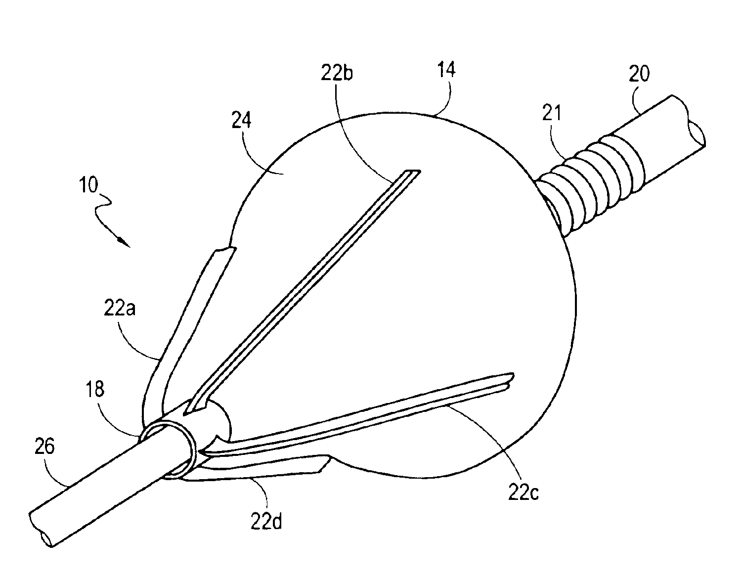
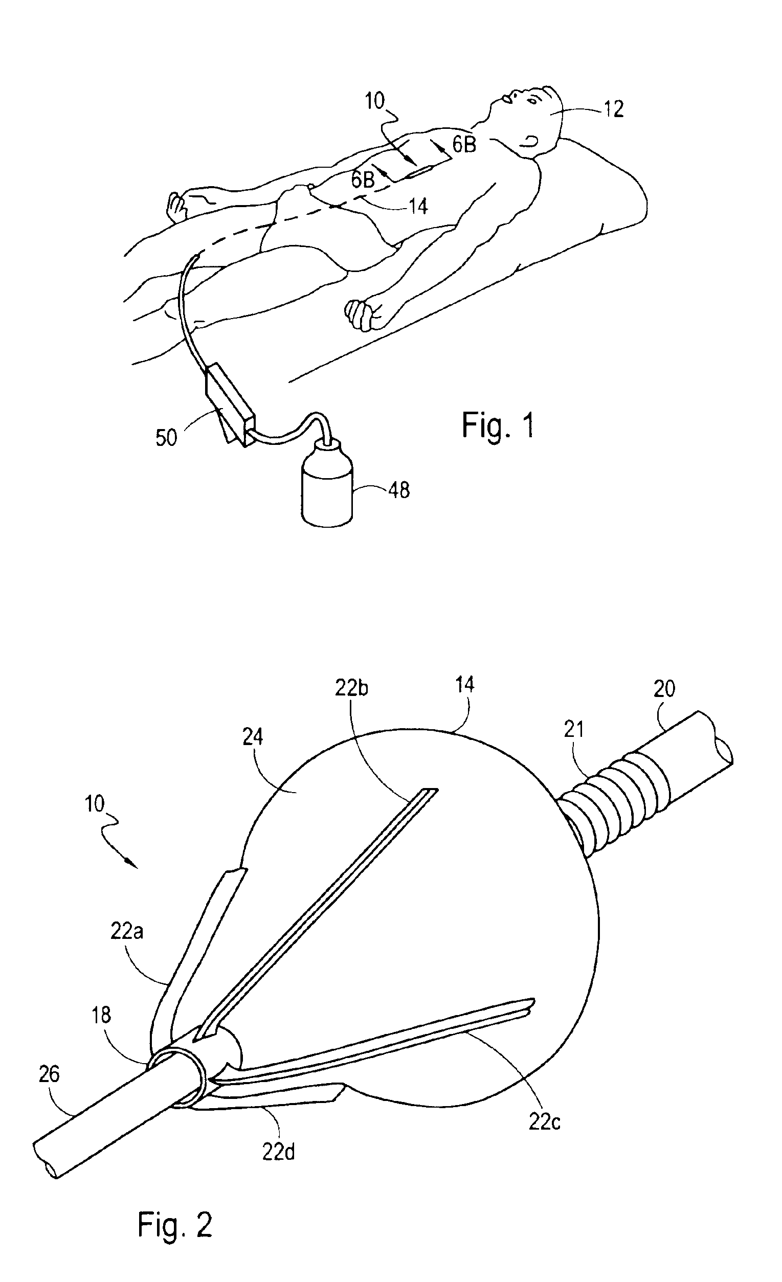
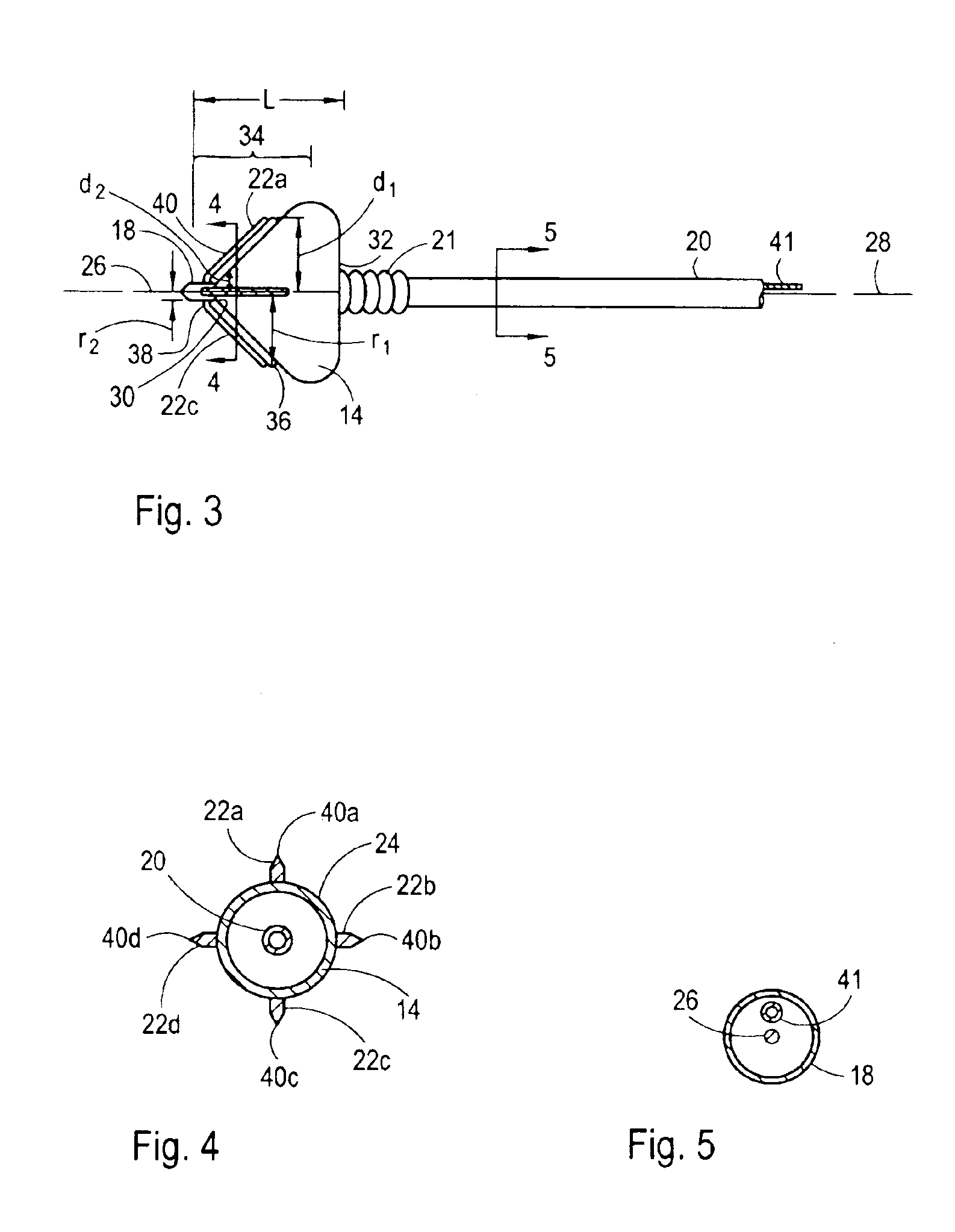
[0006]The present invention is directed to an apparatus for incising and dilating a stenosis within a vascular conduit of a patient. More specifically, the present invention is directed to an apparatus for incising a stenosis with relatively short incising blades that, due to their small size, can be easily guided through the bends and curves of the narrow vascular conduits to the site of the stenosis. For the present invention, the apparatus includes an inflatable balloon that is attached to the distal end of a catheter. The catheter is elongated and defines a longitudinal axis in the direction of elongation. At the distal end of the catheter, the balloon extends axially from a distal end to a proximal end and is formed with an external surface. Also for the present invention, the balloon includes a tapered section that can extend to the distal end of the balloon. More specifically, due to the tapered section, the balloon narrows in the distal direction toward the distal end of the balloon. Consequently, within the tapered section, the external surface of the balloon includes a first point radially distanced from the longitudinal axis at a relatively large distance d1 and a second point, distal to the first point, that is radially distanced from the longitudinal axis at a relatively small distance d2 (d1>d2), when the balloon is inflated.
[0007]In accordance with the present invention, the apparatus further includes one or more incising blades, with each incising blade having a proximal end and a distal end. Each blade is attached to the external surface of the balloon, extending outwardly from the external surface and terminating in a cutting edge. More specifically, each incising blade is attached to the tapered section of the balloon. For the present invention, each incising blade is oriented with the proximal end of the blade radially distanced from the longitudinal axis at a distance r1 and the distal end of the incising blade radially distanced from the longitudinal axis at a distance r2, with r1>r2. As a consequence, the balloon can be inflated to deploy each incising blade into a position where the blade is at an angle relative to the longitudinal axis of the catheter. This cooperation of structure allows the incising blades to cut an incision into a stenosis during axial advancement of the inflated balloon.
[0009]In both the straight blade and curved blade embodiments, the balloon can be shaped wherein a portion of the balloon extends to a greater radial distance than the blades, after the balloon has been inflated. More specifically, the tapered section can extend proximally from the proximal end of each blade. With this cooperation of structure, there will be at least one point on the balloon that is distanced from the longitudinal axis at a distance d with d>r1 after the balloon has been inflated. This cooperation of structure prevents the blades from cutting into or through the wall of the vascular conduit, while allowing the blades to incise a stenosis that protrudes from the wall of the vascular conduit and into the lumen of the vascular conduit.
[0010]To further allow the apparatus to be easily navigated through the vascular conduits of a patient, the catheter can include a flexible coil. In a particular embodiment of the present invention, the flexible coil is positioned proximal to the balloon. In another embodiment of the present invention, the balloon is formed with a cylindrical section that is positioned proximal to the tapered section with at least a portion of the flexible coil positioned inside the balloon. The flexible coil provides lateral flexibility to the apparatus, allowing the blades and at least a portion of the balloon to deflect from the proximal portion of the apparatus during advancement and withdrawal of the apparatus through the vascular conduits. On the other hand, the flexible coil provides good axial stiffness allowing the catheter to be pushed through the vascular conduits. Additionally, the coil is capable of transmitting the axial force required to push the incising blades through a stenosis during an incision.
[0011]In operation, the balloon is first deflated, allowing each blade to assume a position adjacent and parallel to the longitudinal axis. In a particular implementation, each blade is further positioned between adjacent balloon folds to prevent exposure of the cutting edges to the walls of the vascular conduits while the apparatus is navigated through the vascular conduits of the patient. With the balloon deflated, the distal end of the apparatus is inserted into a vascular conduit such as a peripheral artery and advanced through the vasculature until the blades and balloon are positioned in front of a stenosis. For this purpose, a guidewire can be used to establish a mechanical pathway to assist the distal end of the apparatus to the site of the stenosis. Next, the balloon is at least partially inflated causing the balloon and incising blades to move outwardly together in a radial direction from the longitudinal axis. In greater detail, the proximal end of each blade moves a greater radial distance than the distal end of the blade during inflation, positioning the proximal end of each blade at a greater radial distance from the longitudinal axis than the distal end of each incision blade. It is to be appreciated that the proximal end of each blade can be moved to a selected radial distance by controlling the inflation pressure within the balloon.


