Oarlock system

a technology of oarlocks and sleeve, which is applied in the field of oarlocks, can solve the problems of oarlocks that don't give the rower a strong connection with the shell, uneven wear of both sleeves, and loss of valuable time, so as to prevent inadvertent separation of the oar. , the effect of improving the rowing geometry

Inactive Publication Date: 2016-07-19
FLEXOARS CORP
View PDF5 Cites 5 Cited by
  • Summary
  • Abstract
  • Description
  • Claims
  • Application Information

AI Technical Summary

Benefits of technology

[0021]It is yet a further object of the invention to provide an oarlock in which the oarlock swivels around a single axis, rather than an arc, improves rowing geometry.
[0022]It is yet a further object of the invention to provide an oarlock in which a cam system helps position the blade perpendicular (catch) and parallel (recovery) and eliminates the free-play associated with the square-in-square design of traditional oarlocks.
[0023]It is yet a further object of the invention to provide an oarlock in which enclosed cams in the oarlock work with blocks (cam-followers) on the sleeve to prevent inadvertent separation of the oar and the oarlock.
[0024]It is yet a further object of the invention to provide an oarlock in which cutouts on the outside of each cam housing permit the oar to be extracted quickly.
[0025]It is yet a further object of the invention to provide an oarlock when the oar is pulled away from the oarlock and then reinserted 180 degrees out, it can be used for backwatering.
[0026]It is yet a further object of the invention to provide an oarlock in which curved outside walls of the oarlock allow block to easily exit cutout when the oar is rotated with slight Inboard pressure.

Problems solved by technology

There are many problems with existing oarlocks.
When starting of a race from a full stop, valuable time is lost when there is any delay getting the sleeve against the oarlock as the rower applies power to the handle.
The loose fit between the oarlock and sleeve doesn't give the rower a strong sense of connection with the shell.
The square sleeve rotating in the square oarlock causes both to wear unevenly.
Over-rotation of the handle during feathering is possible and can cause severe “crabs” which can literally eject the rower out of the shell.
This loose fitting arrangement can sometimes result in last power if the oar moves vertically in the middle of a stroke, especially in rough water.
A separate component called a collar is positioned around the sleeve and tightened with a tool to set proper inboard, which can be time consuming.

Method used


Image

  • Oarlock system
  • Oarlock system
  • Oarlock system

Examples


first embodiment

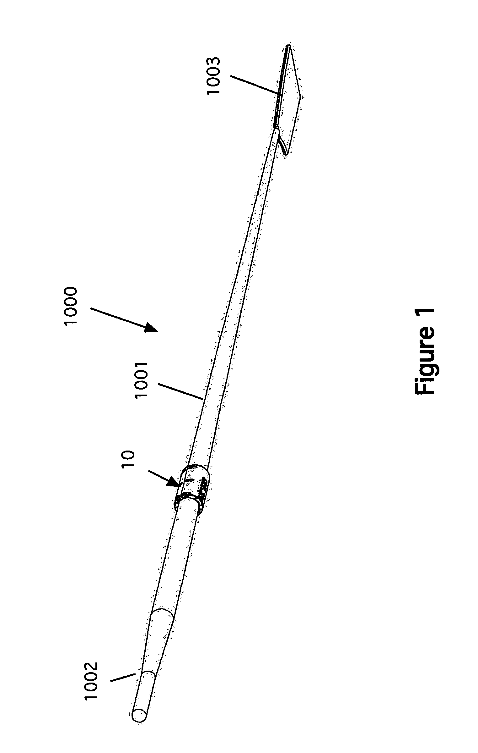
[0077]Referring now to the drawing figures, FIG. 1 is a perspective view of the sleeve portion of the invention installed on an oar.

[0078]The oar 1000 has a shaft 1001, a handle 1002 and a blade 1003. The figure shows a sleeve 10 secured to the shaft of the oar. The sleeve is secured by screws (see, e.g. FIGS. 2 and 3). The operation of the sleeve 10 and its relation to other components are discussed below.

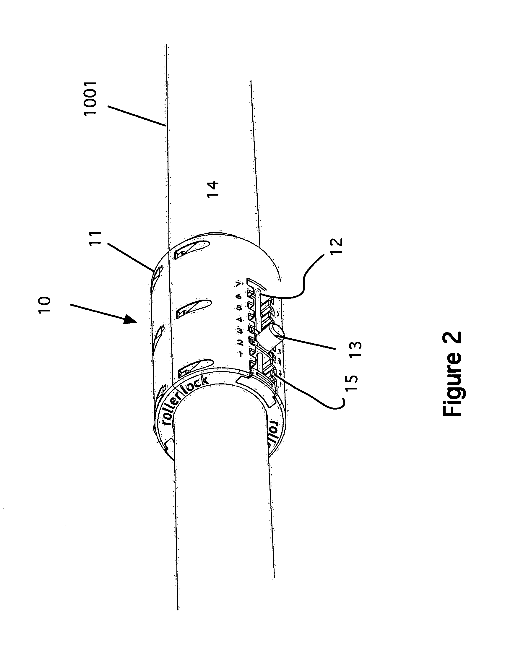
[0079]FIG. 2 is a detail view of a first embodiment of the sleeve and oar assembled. Here, details of the first embodiment sleeve 10 are shown. The sleeve is a formed member that has recesses for fasteners 11 to pass through to hold the sleeve together on the oar shaft 1001. The sleeve provides the critical interface between the oar shaft and the oarlock. Its diameter is just slightly smaller than the oar retainer diameter (discussed below), thereby assuring connection without free play.

[0080]In all embodiments, the sleeve incorporates a longitudinal adjustment channel along its e...

third embodiment

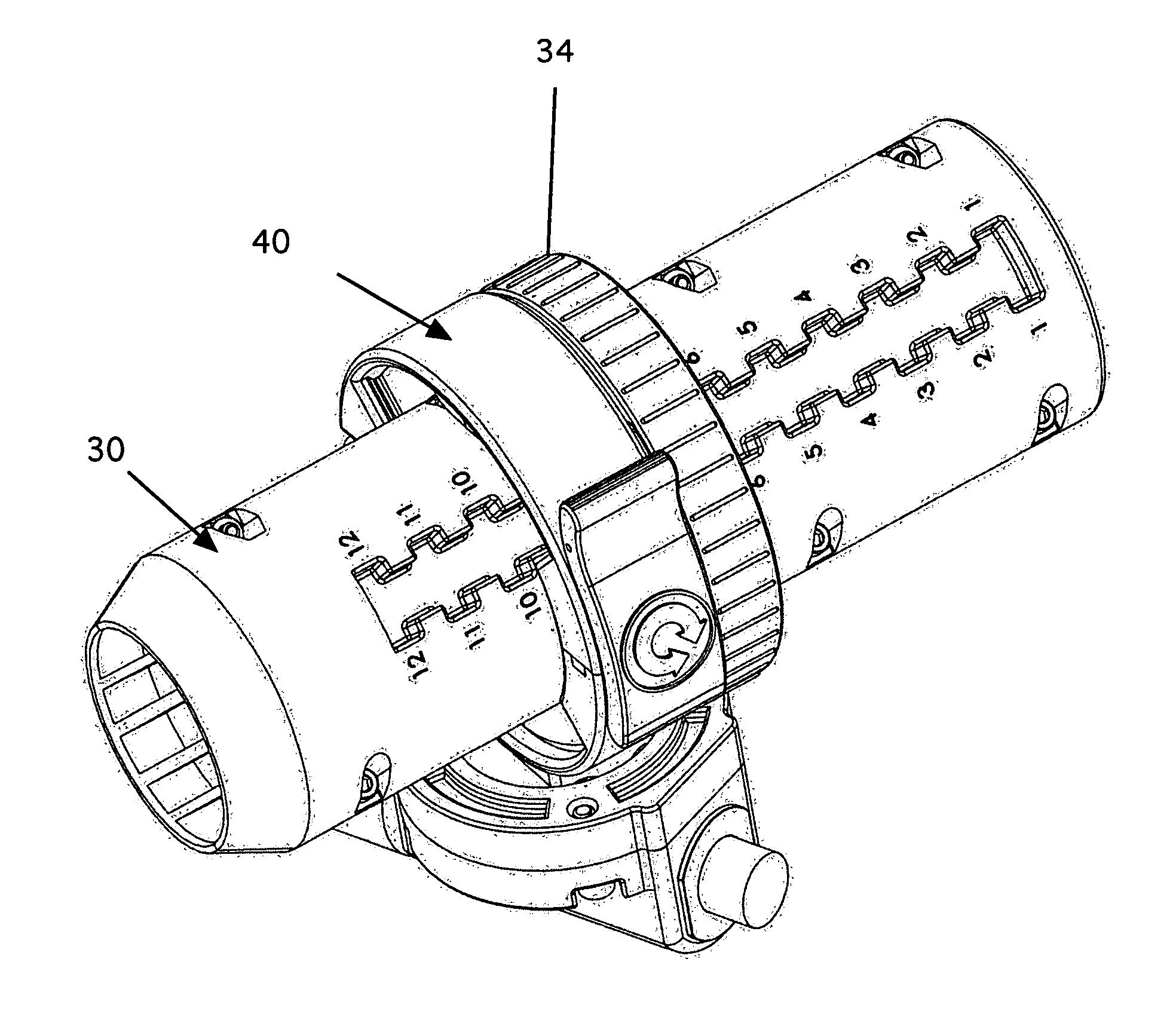
[0086]FIG. 7 is a rear perspective detail of the sleeve and lock of a In the alternate embodiment, the sleeve 30 has two sides as before, secured with fasteners 31. A channel 32 is formed as before with teeth 33. A locking ring (retainer ring) 34 is employed to hold the arrow-shaped blocks 35 in place. This can be considered as a means for temporarily fixing said cam block in a position, as described below. The knurled ring 34 has an inside edge 34a that acts as a tongue and interfaces with a groove 35a in the top of the blocks. (See FIG. 9). When twisted 90 degrees clockwise, the inside edge of the ring gradually tightens on the block 35 because it is slightly out of round and locks the blocks into position. The ring can be removed with a 90-degree twist counter clockwise. Note that with this embodiment, the ring 34 is used to lock both blocks at the same time.

[0087]FIG. 8 is a front detail view of the sleeve and lock of the third embodiment, assembled. In this view, the locking r...

second embodiment

[0105]FIG. 21 is a detail view of the bottom portion of the bottom-only dock of the second embodiment, assembled. FIG. 22 is an exploded detail view of the bottom —only dock. As clearly shown in these two figures, this dock 60 is a curved member having a top, a bottom and a fastener for pivotably securing said oar retainer to the top of said curved member. As before, this embodiment of the dock is secured to the oar retainer using the pivot bolt 60a pivot flat washer 61b, pivot split lock washer 61c, pivot lock nut 51d, and a cover 61e. The entire assembly of the dock 60, the pivot bolt 60a, pivot flat washer 61b, pivot split lock washer 61c, pivot lock nut 51d, and a cover 61e, is considered to be a means for pivotably securing the oar retainer to the top of the dock 60 curved member. The dock is mounted to the rigger via the bottom rigger-mounting bolt 62. A bushing 63 and washer 64 are also used as shown. All of these are considered to be a fastener means for securing the dock 60...


PUM


Abstract

The invention is made up of three major components, a sleeve that is mounted on an oar shaft; a dock, which is mounted to the shell's riggers; and a pair of oar retainers that clamp around the sleeve and pivotally mount to the dock. The sleeve is locked into the oar retainers via a latch. The sleeve has a movable block that has a cam, which engages grooves in the oar retainers. The sleeve and can rotate around its axis, which allows the oar to be feathered. The oar retainers hold the sleeve and allow it to rotate and pivot during the rowing stroke. The dock attaches the oar retainer to the shell or outrigger. Its purpose is twofold: first, it provides a stable vertical platform on which the oar retainers can pivot up and down; second, it swivels left and right.

Description

CROSS REFERENCE TO RELATED APPLICATIONS[0001]This application claims benefit of Provisional applications 61 / 284,073 filed Dec. 11, 2009, and 61 / 401,451 filed Aug. 13, 2010.STATEMENT REGARDING FEDERALLY SPONSORED RESEARCH AND DEVELOPMENT[0002]Not ApplicableBACKGROUND OF THE INVENTION[0003]1. Field of the Invention[0004]This invention relates to oarlocks and particularly to oarlocks with adjustable control features.[0005]2. Description of the Prior Art[0006]In recreational or competitive rowing, it is desirable to be as efficient as possible for the purpose of conserving energy. In competitive events called regattas, the rowers, use their legs and arms to propel the boat towards the finish line. Winning requires strength, endurance, technique and, in anything but a single scull, teamwork. It also requires equipment that will efficiently transfer their energy into propulsion.[0007]It is important therefore to make sure that each piece of gear on the shell is tuned for maximum performan...

Claims


Application Information

Patent Timeline
Patent Type & Authority Patents(United States)
IPC IPC(8): B63H16/073B63H16/04
CPCB63H16/073B63H2016/043
Inventor HORAN, RICHARD
Owner FLEXOARS CORP
Why Eureka
Try Eureka