Ground anchor with tilt compensation

a technology of tilt compensation and ground anchors, applied in the field of ground anchors, can solve the problems of lack of adjustability, the inability to precisely align consecutive posts, and the tilt of posts mounted into sockets, and achieve the effect of easy straightening

Active Publication Date: 2016-07-19
PAANANEN TUOMO
View PDF56 Cites 10 Cited by
  • Summary
  • Abstract
  • Description
  • Claims
  • Application Information

AI Technical Summary

Benefits of technology

[0018]By utilizing a compensation plate described here, even significant tilting of the ground anchor can be compensated for in order to achieve a completely vertical post.
[0019]Another benefit of the invention is that if the post is tilted at a later stage due to ground frosting or otherwise, the post can easily be straightened by loosening the compensation plate bolts, correcting the position of the post, and by re-tightening the bolts.

Problems solved by technology

A drawback, however, is its lack of adjustability: each standard size post requires its own fixed anchor / socket combination.
It is practically impossible to align consecutive posts exactly.
A drawback is that when the wedge is slightly tilted during ramming, the post mounted into the socket will also be tilted.
In practice, however, bending the flanges is not easy, particularly if the L-brackets are made of thick steel plate.
This may result in an uneven bending of the flanges, making it nearly impossible to make the flanges parallel to each other.
In fence construction it happens very often that the ground anchor hits a rock during ramming which causes tilting of the anchor.
This, subsequently, results in a tilted post.

Method used


Image

  • Ground anchor with tilt compensation
  • Ground anchor with tilt compensation
  • Ground anchor with tilt compensation

Examples


Embodiment Construction

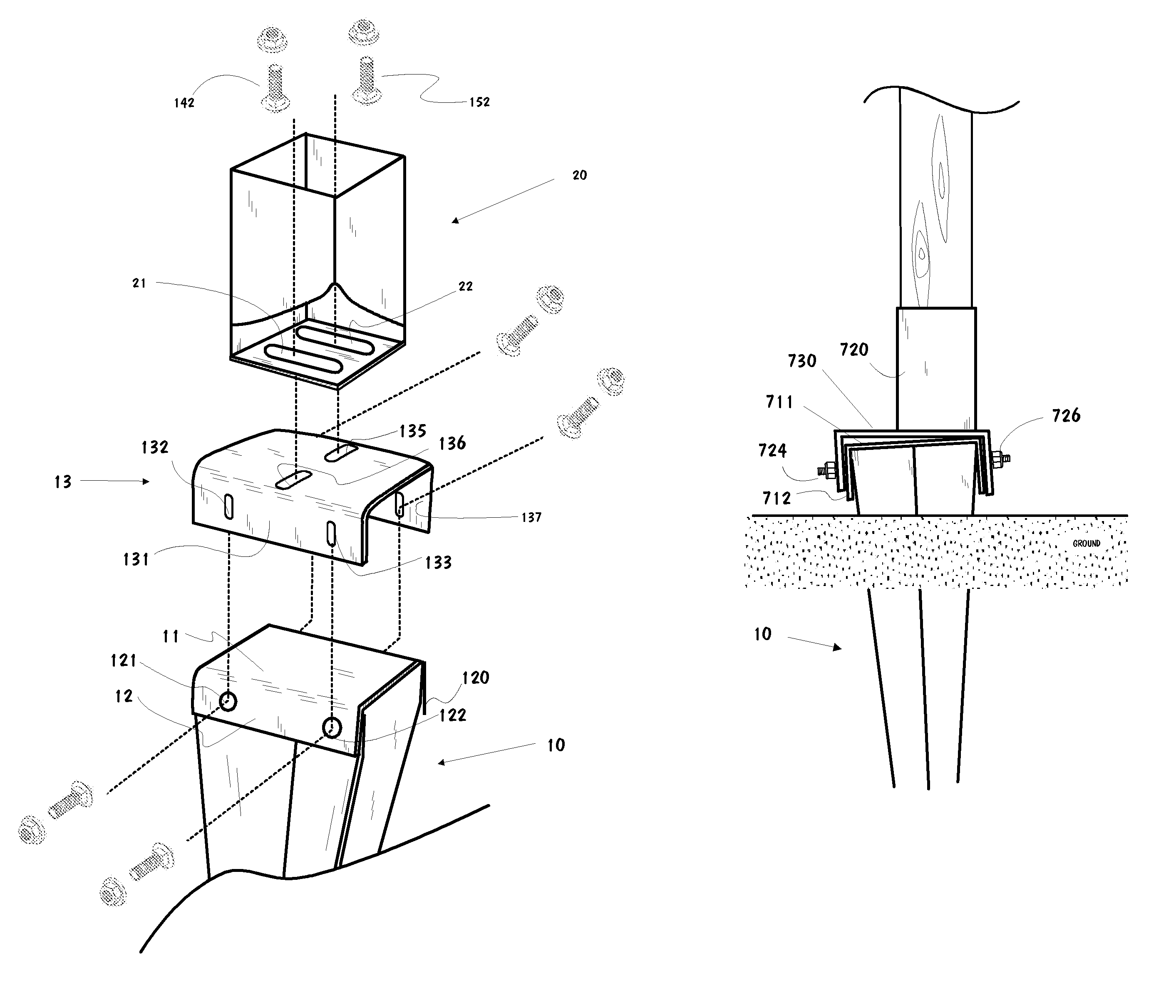
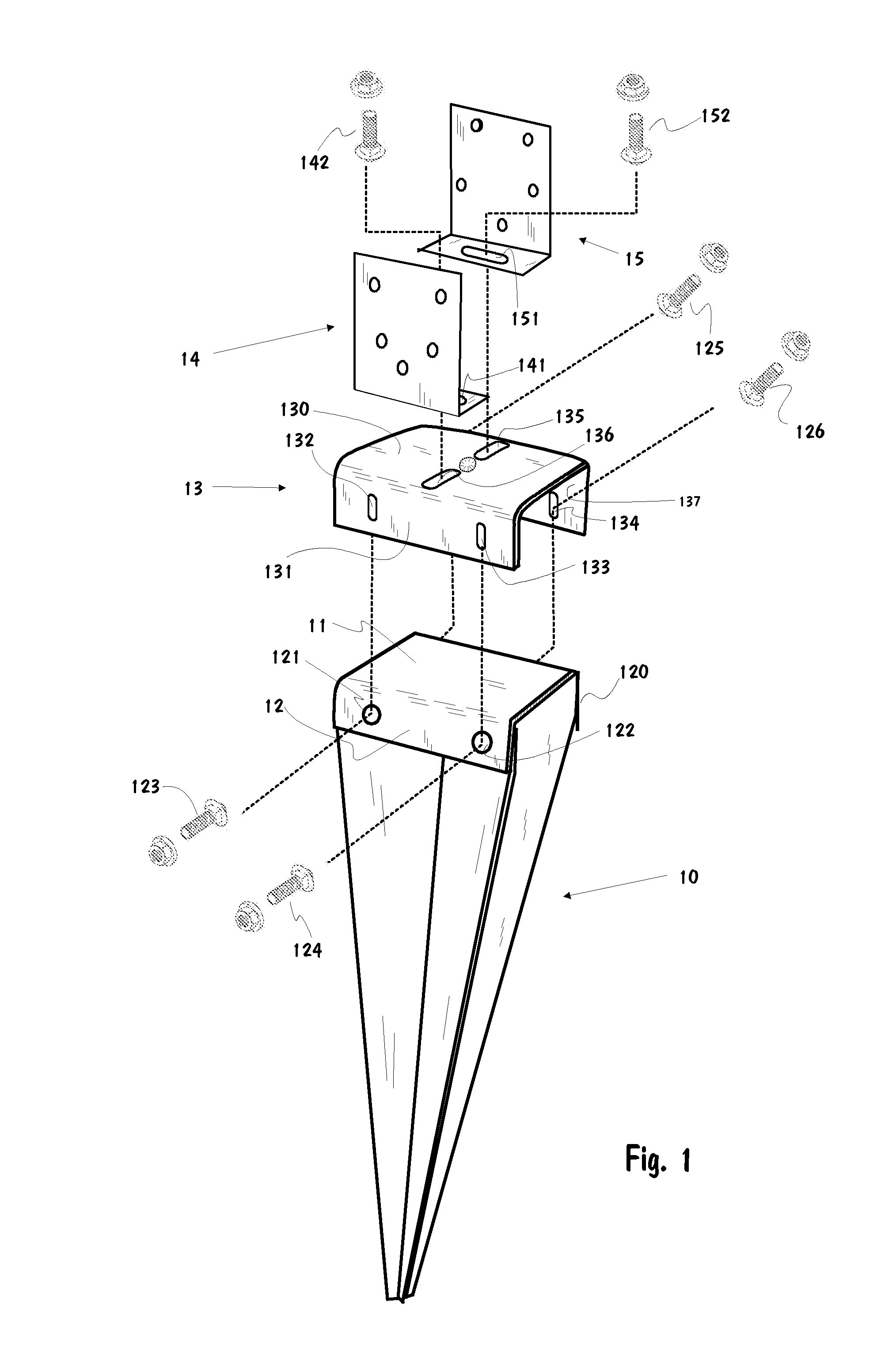
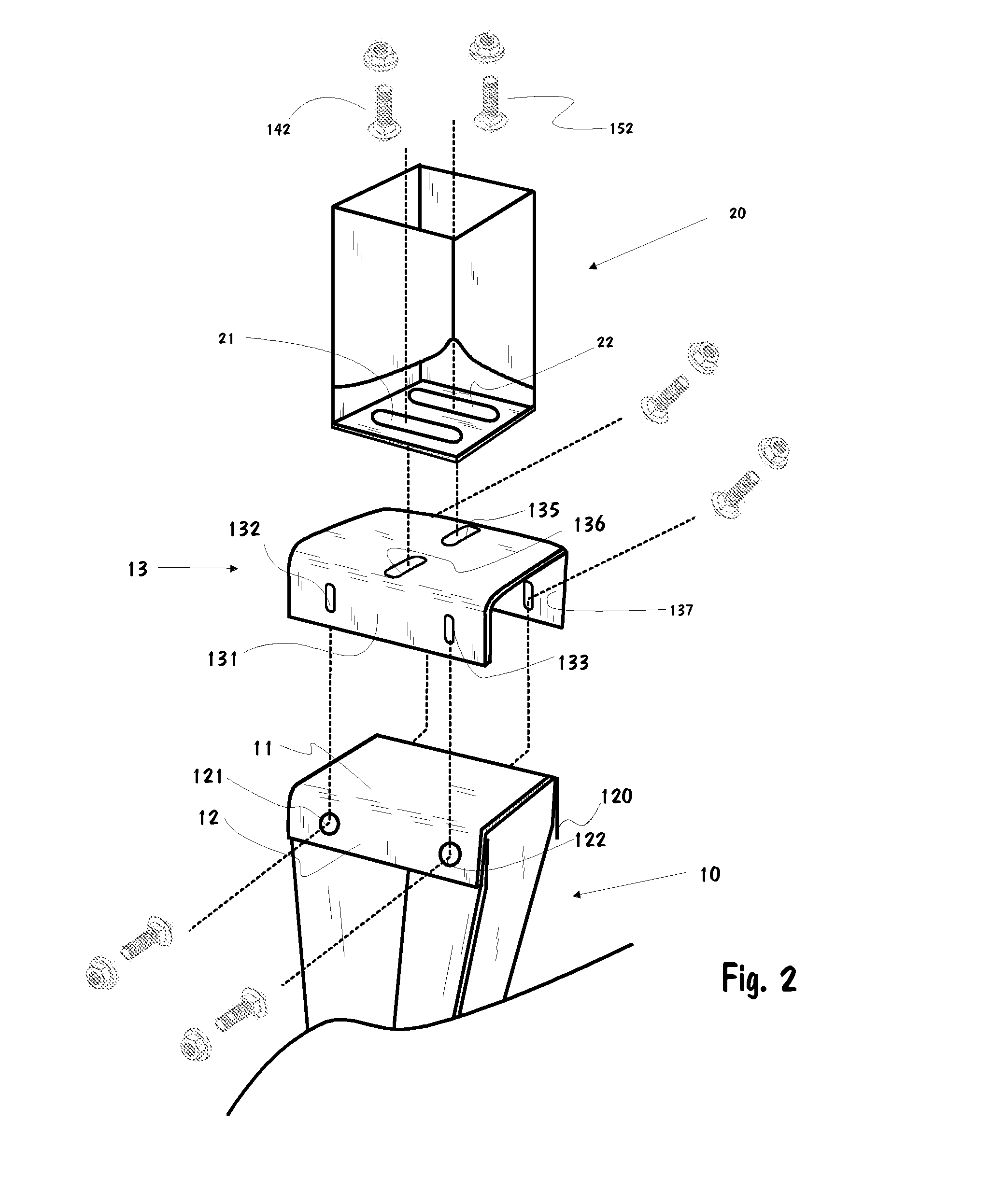
[0033]FIGS. 1 and 2 depict exploded views of a ground anchor with tilt compensation according to the invention: all parts are made of steel.

[0034]The ground anchor in FIG. 1 comprise traditional anchor part 10, consisting of the commonly used wedge-shaped steel plates welded together. The anchor part is wedge-shaped, making it easier to ram into the ground, but it can also feature a screw, in which case it is screwed into the ground.

[0035]On the top of anchor part 10 is welded a top plate 11 for receiving ramming strokes and transferring the force to the anchor part while protecting the flanges against bending. While the use of a top plate is known, the invention encompass an end plate which has downwards-bent edges forming flanges on opposite sides, only one downwards-bent flange 12 is shown in FIG. 1, each flange having at least one hole. Flange 12 depicted here has two holes: 121 and 122.

[0036]A post or pillar, not depicted in the figure, is mounted on the mounting part. In FIG. ...


PUM


Abstract

During ramming of a metal ground anchor for a fence post by applying force on its top plate, the anchor is often tilted, subsequently resulting in the tilted fence post. The tilt is compensated by utilizing a compensation plate (13), the dimensions and form of which correspond to the dimensions and form of the top plate (11) welded onto the ground anchor (10). The compensation plate is located above the top plate (11) and a post holder (2) is attached thereto. Downwards-protruding mounting flanges (131, 137) are located on two opposite edges of the compensation plate, aligning with downwards-protruding fixing flanges of the top plate. Elongated adjustment slots (132, 133) in the mounting flanges are aligned with holes in the fixing flanges of the top plate, enabling the flanges to be attached with bolts. The adjustment slots allow adjusting the compensation plate before the bolts are tightened.

Description

TECHNICAL FIELD[0001]This invention features a ground anchor which can be rammed or screwed into the ground, and has a screw or wedge on the lower part and a post socket on the upper part.BACKGROUND ART[0002]For installing light pillars, such as fence posts, it is used a zinc-coated steel anchor consisting of a wedge-shaped ground-protruding portion and a welded socket on its top, wherein the pillar is inserted into the socket. Posts of different diameters require different sizes of ground anchors. A benefit of this type of ground anchor is its simple, affordable structure and ease of installation. A drawback, however, is its lack of adjustability: each standard size post requires its own fixed anchor / socket combination. Furthermore, this type of ground anchor must be rammed into the ground completely vertically and precisely in the right point. Otherwise the Fence post may be skewed and displaced from the right point. It is practically impossible to align consecutive posts exactly....

Claims


Application Information

Patent Timeline
Patent Type & Authority Patents(United States)
IPC IPC(8): E04H12/22E04H17/22E04H12/34
CPCE04H12/347E04H12/2215E04H12/2269E04H17/22E04H12/2284E04H17/009
Inventor PAANANEN, TUOMO
Owner PAANANEN TUOMO
Why Eureka
Try Eureka