Comber

A combing machine and headstock technology, which is applied in the field of combing machines, can solve problems such as unreasonable gripping lip shape, affecting the combing effect of combing machines, and large volume of master and master motors, so as to reduce work intensity and cost, The effect of compact structure and large braking torque

Inactive Publication Date: 2002-07-03
山西经纬合力机械制造公司总厂
View PDF0 Cites 9 Cited by
  • Summary
  • Abstract
  • Description
  • Claims
  • Application Information

AI Technical Summary

Problems solved by technology

[0011] 1. Solve the problem of large starting current of ordinary motors, which is unfavorable to the life of the motor, and the problems of large size and complex structure of the mother and child motor, and the wear and tear of the brake rubber ring and the fai

Method used


Image

  • Comber
  • Comber
  • Comber

Examples


Embodiment Construction

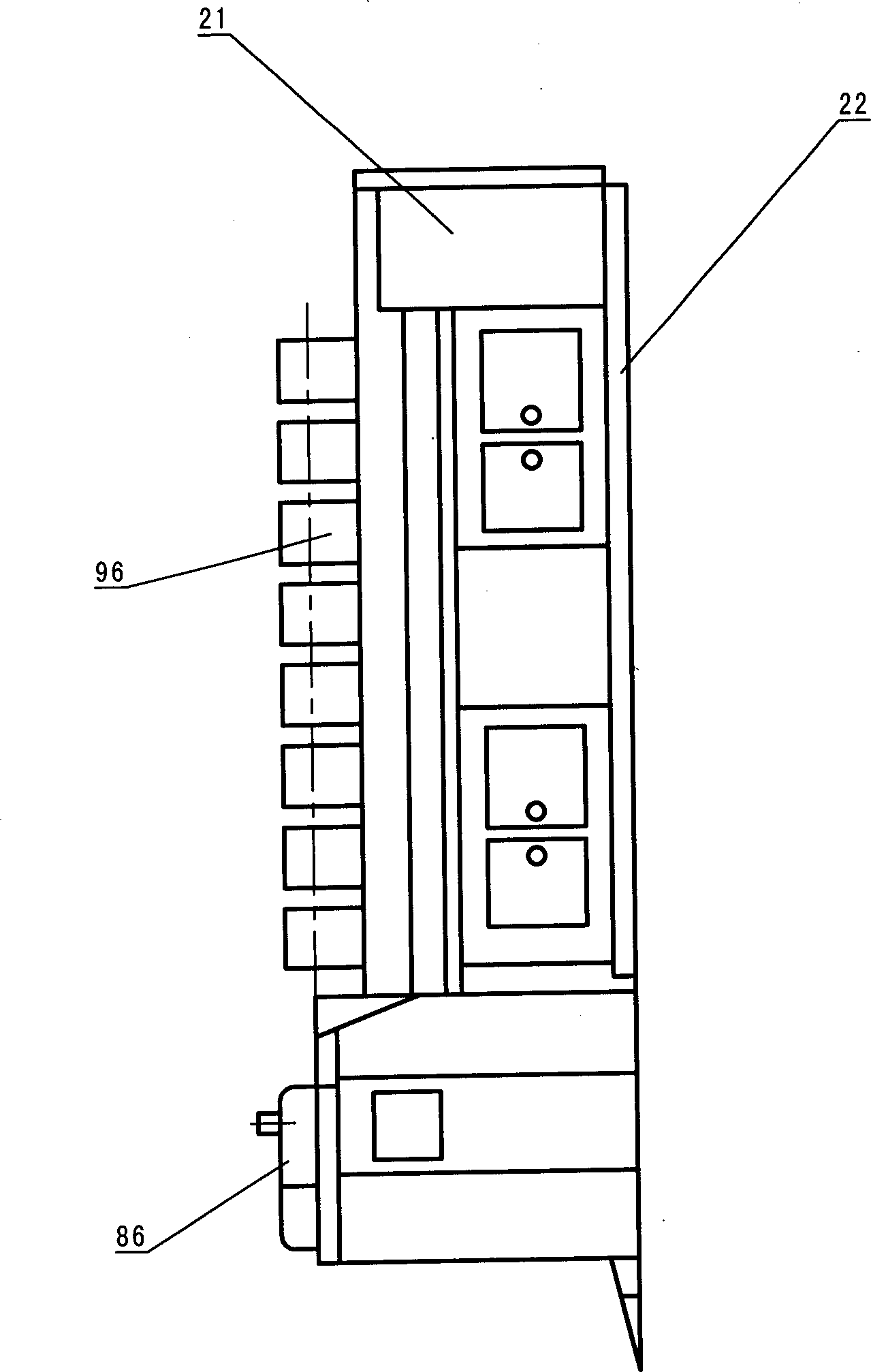
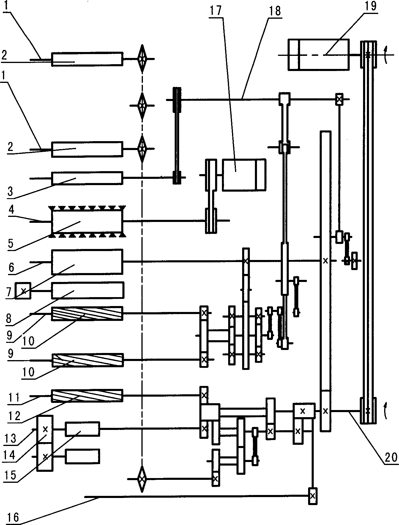
[0050] The combing machine is mainly composed of head unit, main drive unit, carding unit, tail unit, electrical control unit and so on.

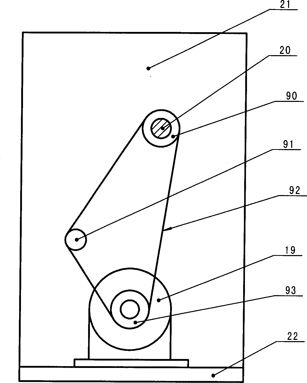
[0051] The headstock device is connected by the main motor 19 with the main transmission shaft 20 through the belt; the main transmission shaft 20 is connected with the output roller shaft 11 and the pressure roller shaft 13 at its output end through the gear transmission mechanism; the main transmission shaft 20 is connected with the cylinder through the gear pair. The shaft 6 is connected; the cylinder shaft 6 is connected with the separation roller shaft 9 through the gear transmission and the linkage mechanism; the cylinder shaft 6 is connected with the nipper shaft 18 through the rocker mechanism; the nipper shaft 18 is connected with the tension shaft 3 through the gear set; The main shaft 20 is connected with the roll roller shaft 1 by a gear transmission mechanism and a chain; a brush motor 17 is also provided in the headstock, which...


PUM


Abstract

A comber for carding and straightening cotton fibres is composed of geared head, main driver, carding unit, tail unit and electric controller. It features use of dual-speed motor, electromagnetic braking, two-point grasp of jaws for decreasing loss of long fibres, pneumatic pressing, lower curve stretching for higher uniformity, centralized suction of dropped fibres, PCL control, failure display and photoelectric detection with higher sensitivity.

Description

[0001] 1. Fields: [0002] The invention relates to a combing machine used in cotton spinning engineering. 2. Background technology: [0003] At present, there are A201 series and FA251 series combing machines in China. There are E7 / 4, E7 / 5, E7 / 6 series combing machines abroad. Both use ordinary motors or mother-in-law motors to provide power. [0004] Using ordinary motors, the starting torque is much greater than the running torque, and the current is too large during starting, which affects the service life of the motor. If a high-power motor is used, it will be wasted during normal operation, and the volume will also increase. Due to the above problems, some manufacturers have changed to adopt the form of sub-mother motors, but a two-stage gearbox is required, which increases the difficulty of processing and manufacturing costs; at the same time, it is necessary to add a sub-motor to the main motor, which also increases the volume. To be redesigned. When the master mot...

Claims


Application Information

Patent Timeline
IPC IPC(8): D01G19/00D01G19/16
Inventor 梁玉虎张莉孙东生苗凌巩建兵张庆生
Owner 山西经纬合力机械制造公司总厂
Why Eureka
Try Eureka