
Eccentric rotator and flat type motor having same

An eccentric rotor, eccentric technology, applied in the shape/style/structure of winding conductors, electrical components, electromechanical devices, etc., can solve problems such as efficiency deterioration, and achieve the effects of reducing bearing loss, sufficient starting torque, and less pressing cost.

Inactive Publication Date: 2007-01-31
TOKYO PARTS IND CO LTD
View PDF6 Cites 0 Cited by
  • Summary
  • Abstract
  • Description
  • Claims
  • Application Information

AI Technical Summary

Problems solved by technology

However, this structure worsens efficiency by inserting a resistor that has no effect on torque

Method used


Image

  • Eccentric rotator and flat type motor having same
  • Eccentric rotator and flat type motor having same
  • Eccentric rotator and flat type motor having same

Examples


Embodiment Construction

[0038] Hereinafter, the configuration of the present invention will be described with reference to various embodiments shown in the drawings.

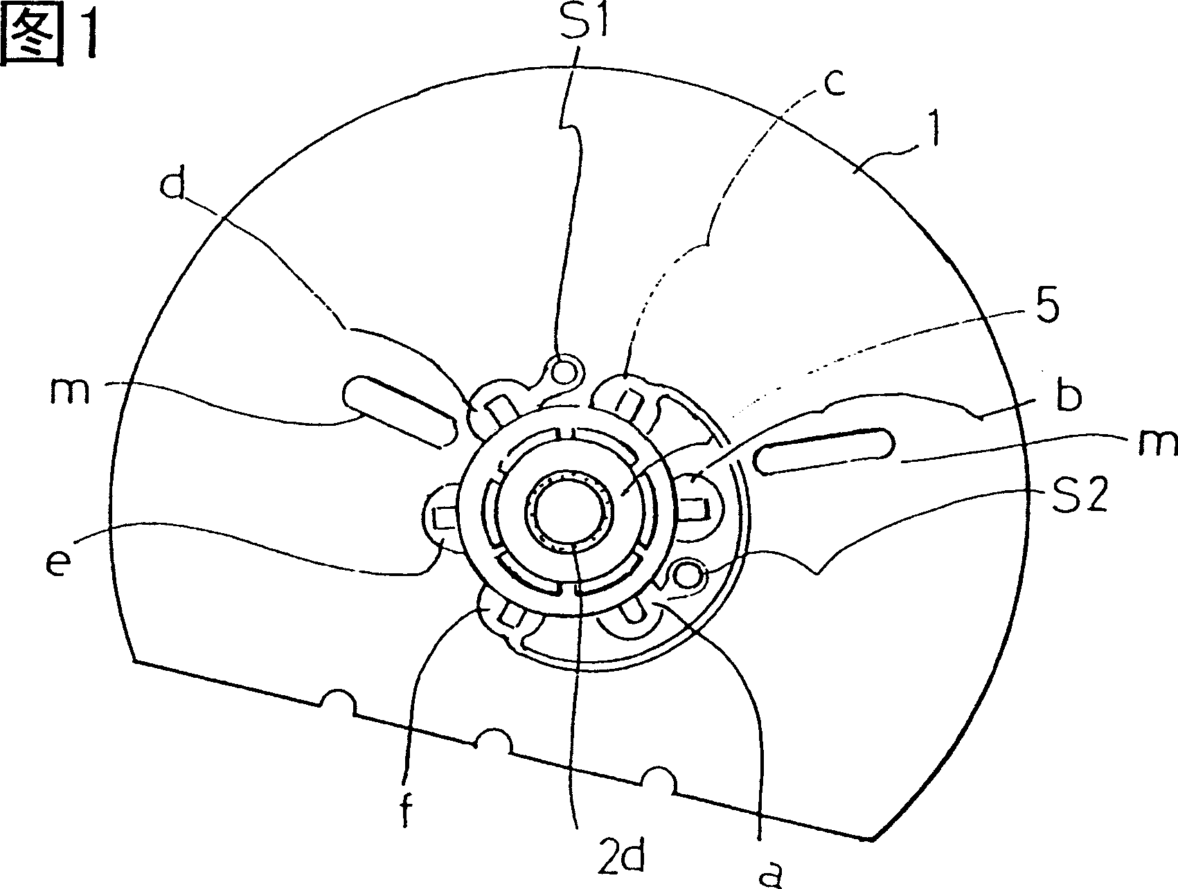
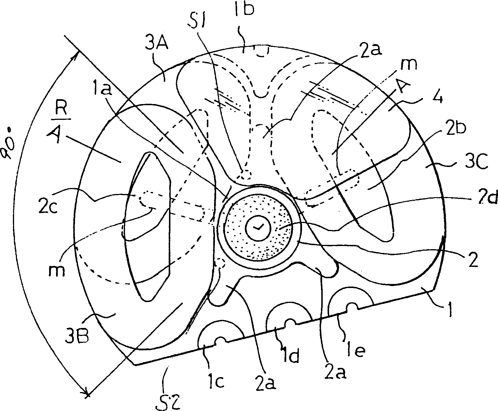
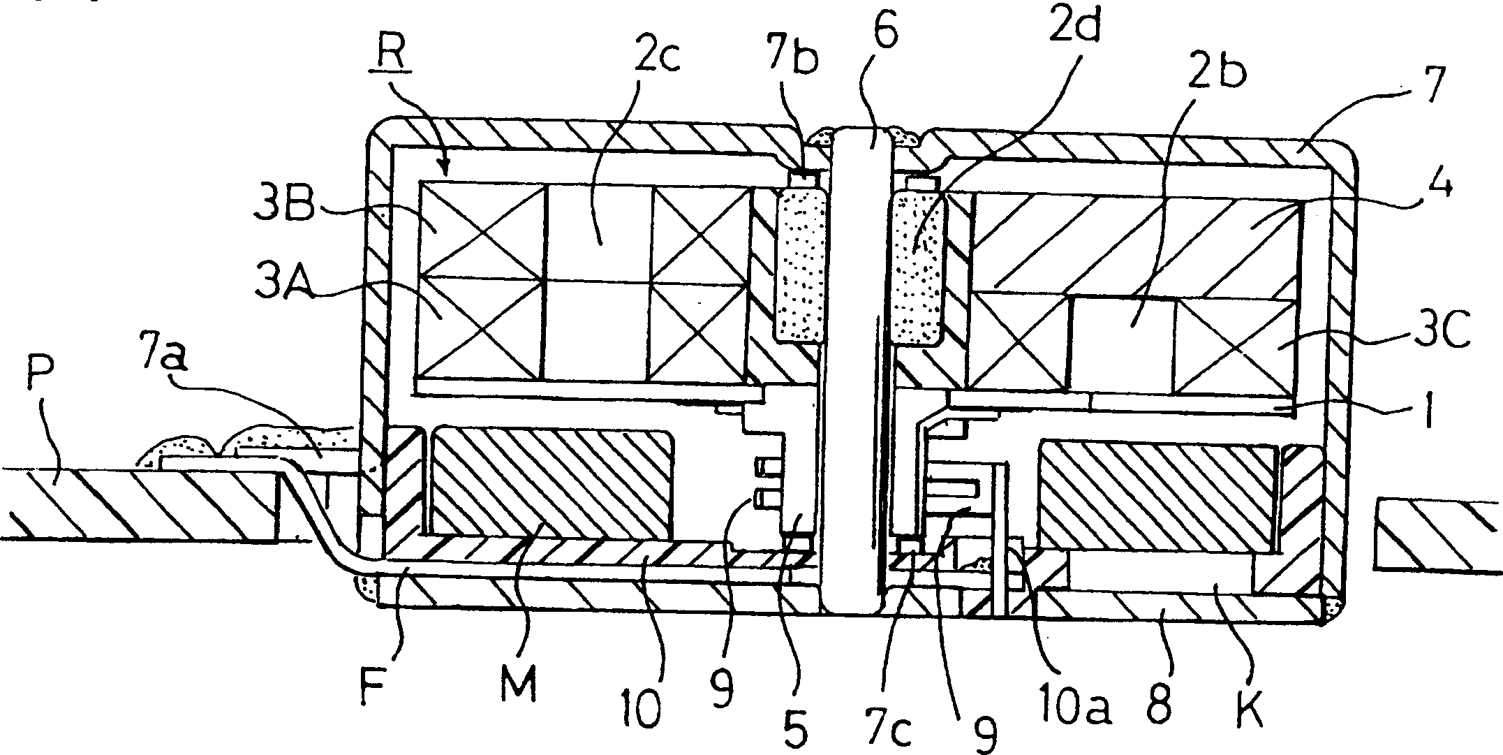
[0039] Fig. 1 is a plan view showing a main part of an eccentric rotor according to a first embodiment of the present invention, viewed from a commutator side. figure 2 is a plan view of the main part of the above-mentioned eccentric rotor viewed from the side opposite to the commutator. image 3 Yes means cut off by line A-A figure 2 It is a cross-sectional view of the flat vibration motor of the present invention housed in the state of the rotor shown. Figure 4 is image 3 An explanatory diagram of the operation of the shown motor. 5 is a plan view showing an eccentric rotor according to a modified example of the first embodiment. Fig. 6 is a plan view showing the main parts of the eccentric rotor according to the second embodiment, seen from the commutator side. Figure 7 It is a longitudinal sectional view of the flat vibrat...


PUM


Abstract

PROBLEM TO BE SOLVED: To get a large quantity of vibrations by getting high efficiency and facilitating the assembly while properly generating the vibrations by centrifugal force, and arranging the eccentric weight here, utilizing the arrangement structure of an air-core coil.SOLUTION: This unit has first, second, and third air-core coils (3A, 3B, and 3C) whose effective conductors are open as far as roughly the magnetization opening angle of the magnetic pole of a magnet, and a commutator (5) is arranged at the center, and this further has a resinous axial holder (2) on the other side of this commutator, and the above first and the second air-core coils are superposed upon each other, being slit by about 30° to 60° in arrangement opening angle, and the third air-core coil is slit by 120° from the first coil not to be superposed upon it.

Description

technical field [0001] The present invention relates to the improvement of a flat vibrating motor used in a silent pager of a mobile communication device and an eccentric rotor as its main component. Background technique [0002] Silent pagers such as known thin or portable telephone set so far are such Figure 10 As shown, an eccentric balance weight W made of tungsten alloy is disposed on the output shaft S of a cylindrical DC motor M, and the eccentric balance weight W is vibrated by utilizing the difference in centrifugal force during rotation. [0003] However, since the eccentric weight W is added to the above-mentioned conventional output shaft S, there is a problem that, on the machine side such as a flat type, it is necessary to consider the swing space of the eccentric weight W and the like. These problems restrict the design; since the above-mentioned balance weight uses high-priced tungsten alloy, there is also a cost problem. [0004] Recently, it has been dema...

Claims


Application Information

Patent Timeline
Patent Type & Authority Patents(China)
IPC IPC(8): H02K7/075B06B1/04B06B1/16H02K7/065H02K23/54
CPCH02K3/22H02K3/26H02K7/063H02K2203/03
Inventor 山口忠男小柳尚久八岛哲志
Owner TOKYO PARTS IND CO LTD
Learn More