
Image forming apparatus with improved timing for emitting beam detect light beam

a technology of image forming apparatus and light beam, which is applied in the direction of electrographic process apparatus, mountings, instruments, etc., can solve the problems of increasing the number of parts that form the light scanning apparatus and increasing the cos

Active Publication Date: 2016-07-26
CANON KK
View PDF12 Cites 25 Cited by
  • Summary
  • Abstract
  • Description
  • Claims
  • Application Information

AI Technical Summary

Benefits of technology

[0007]Therefore, the present invention provides an image forming apparatus, which identifies a reflection surface of a rotary polygon mirror without causing marking back to occur on a recording medium.

Problems solved by technology

This may increase the number of parts that form the light scanning apparatus, and causes an increase in cost.

Method used


Image

  • Image forming apparatus with improved timing for emitting beam detect light beam
  • Image forming apparatus with improved timing for emitting beam detect light beam
  • Image forming apparatus with improved timing for emitting beam detect light beam

Examples


Embodiment Construction

[0038]Now, an embodiment for carrying out the present invention will be described.

[0039][Image Forming Apparatus]

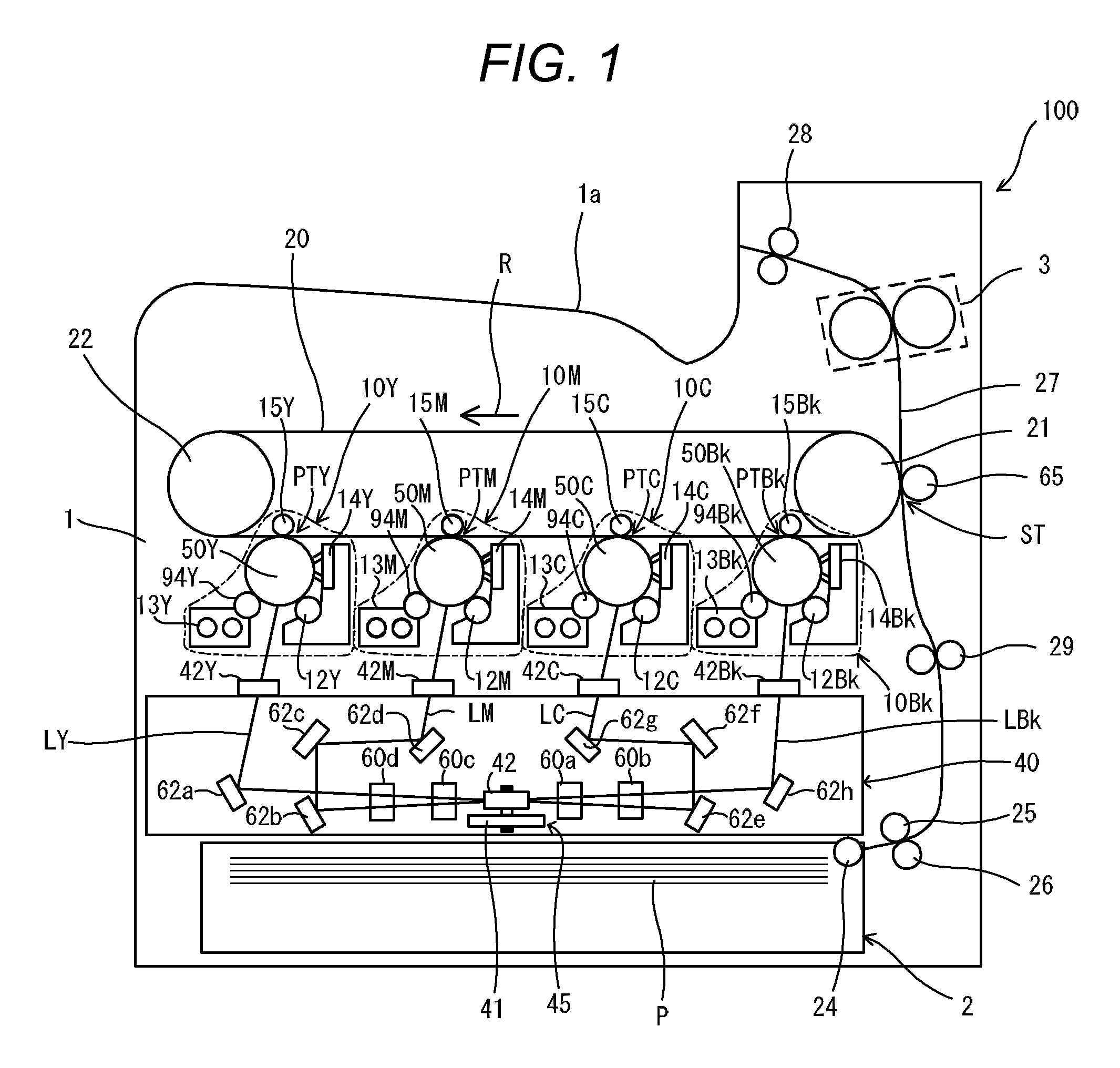
[0040]An electrophotographic image forming apparatus (hereinafter referred to as “image forming apparatus”) 100 according to the embodiment will be described. FIG. 1 is a sectional view of the image forming apparatus 100. As an example of the image forming apparatus 100, a tandem-type color laser beam printer is illustrated. The image forming apparatus 100 is configured to form an image on a recording medium (hereinafter referred to as “sheet”) P using an electrophotographic method. The image forming apparatus 100 includes four image forming portions 10 (10Y, 10M, 10C, 10Bk). The suffixes Y, M, C, and Bk of the reference symbols indicate yellow, magenta, cyan, and black, respectively. In the following description, the suffixes Y, M, C, and Bk may be omitted.

[0041]The image forming portions 10 each include a photosensitive drum serving as an image bearing member (hereinaft...


PUM


Abstract

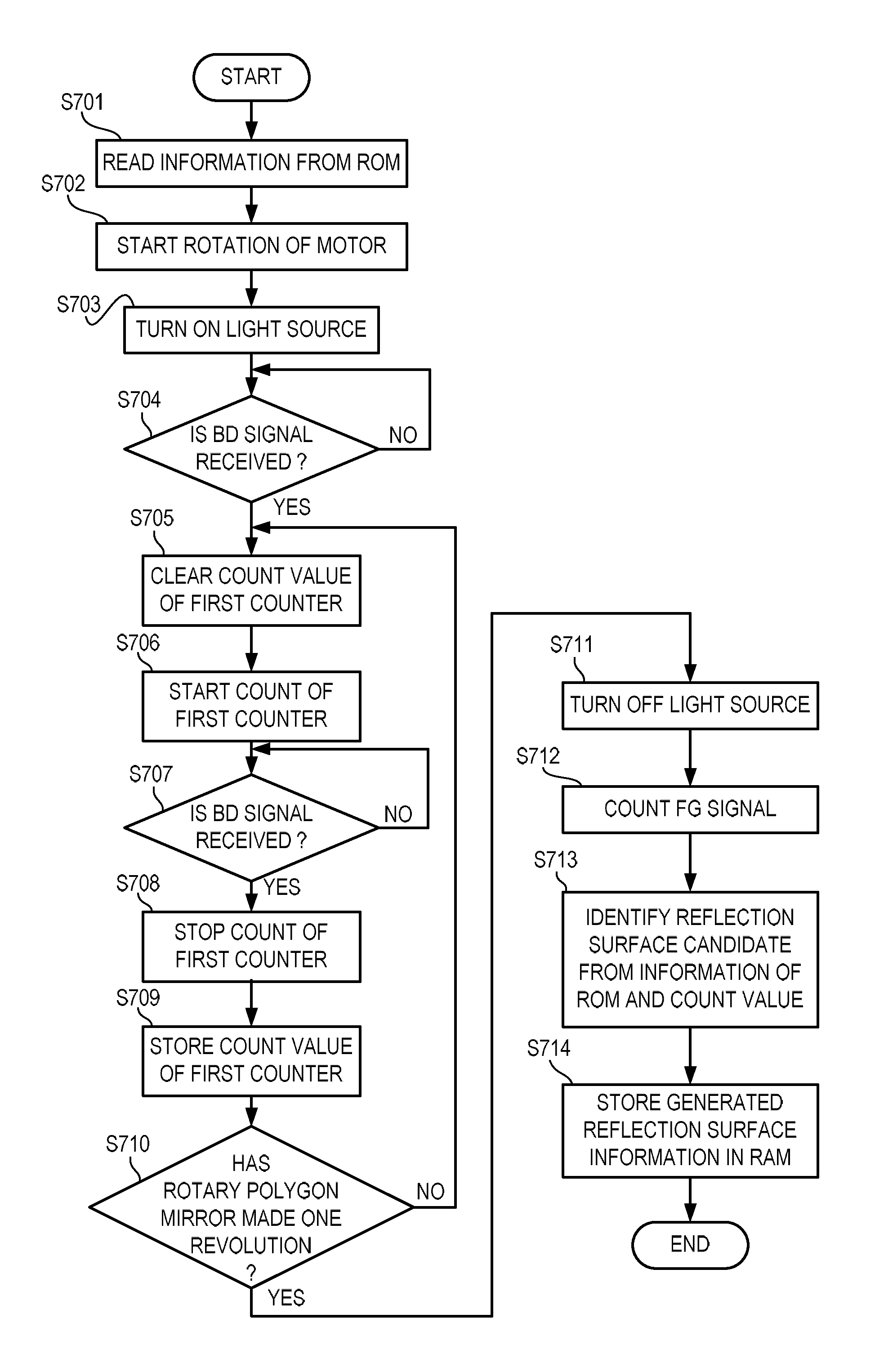
An image forming apparatus including: a photosensitive member; a charging unit; a light scanning apparatus configured to emit a light beam to scan the photosensitive member to form a latent image; and a developing unit configure to develop the latent image. The light scanning apparatus includes a light source, a rotary polygon mirror, a light receiving unit, and a signal generating unit. An incident timing when the light beam deflected by the polygon mirror enters the light receiving unit after the photosensitive member is charged by the charging unit and after a voltage is applied to a toner carrying member by the developing unit is identified based on the number of second signals generated by the signal generating unit between the first signal and the first signal generated by the light receiving unit before the photosensitive member is charged and before the voltage is applied to the toner carrying member.

Description

BACKGROUND OF THE INVENTION[0001]1. Field of the Invention[0002]The present invention relates to an image forming apparatus including a light scanning apparatus.[0003]2. Description of the Related Art[0004]Hitherto, an electrophotographic image forming apparatus such as a digital copying machine, a laser beam printer, or a facsimile apparatus includes a light scanning apparatus. The light scanning apparatus scans a surface of a photosensitive member with a light beam to form an electrostatic latent image on the photosensitive member. The light scanning apparatus includes a light-receiving element configured to receive the light beam deflected by a rotary polygon mirror. The light-receiving element generates a synchronous signal by receiving the light beam. The image forming apparatus emits the light beam based on image data with reference to the synchronous signal, to thereby match scan starting positions of the light beam in a scanning direction thereof with one another among respe...

Claims


Application Information

Patent Timeline
Patent Type & Authority Patents(United States)
IPC IPC(8): B41J2/385H01J29/70B41J2/435B41J27/00G02B26/08G02B26/12G03G15/043G02B7/182
CPCG03G15/043G02B26/121G02B26/127G02B7/1821
Inventor SATO, KAZUMISEKI, HIROTAKAISHIDATE, TAKEHIROIMAI, YUICHIROOTOGURO, YASUAKI
Owner CANON KK
Learn More