Organizer tray, fiber-routing assembly, and electro-optical module

a technology of optical fibers and organizers, applied in the direction of optical light guides, fibre mechanical structures, instruments, etc., can solve the problems of large communication systems, difficult management and routing of optical fibers through the system, and excessive space requirements of substrates in the communication system

Active Publication Date: 2016-08-02
TYCO ELECTRONICS LOGISTICS AG (CH)
View PDF18 Cites 2 Cited by
  • Summary
  • Abstract
  • Description
  • Claims
  • Application Information

AI Technical Summary

Problems solved by technology

Communication systems, such as routers, servers, switches, data centers, and the like, may be large, complex systems that have a number of devices interconnected to one another.
Due to the number of optical fibers in a system and the nature of the optical fibers, it can be challenging to manage and route the optical fibers through the system.
The substrates may require an excessive amount of space within the communication system that might otherwise be used for other components.

Method used


Image

  • Organizer tray, fiber-routing assembly, and electro-optical module
  • Organizer tray, fiber-routing assembly, and electro-optical module
  • Organizer tray, fiber-routing assembly, and electro-optical module

Examples


Embodiment Construction

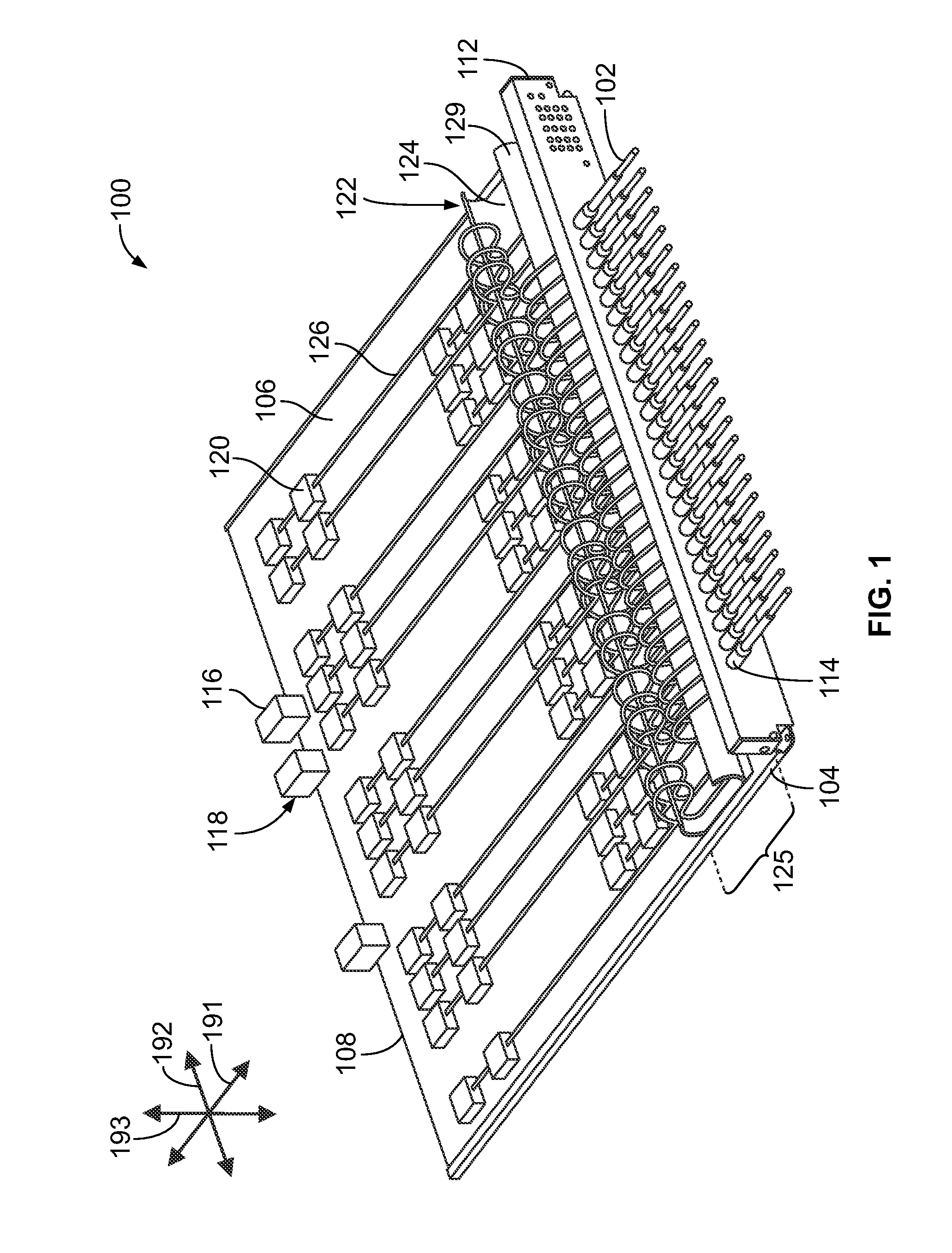
[0018]FIG. 1 is a perspective view of an electro-optical (EO) module 100 formed in accordance with an embodiment. The EO module 100 is configured to communicatively engage one or more optical cable assemblies 102. In FIG. 1, the EO module 100 is oriented with respect to mutually perpendicular axes 191-193, including a mating axis 191, a lateral axis 192, and an elevation axis 193. It should be understood that the EO module 100 is not limited to any particular orientation with respect to gravity. The EO module 100 includes a support frame or panel 104 and a printed circuit board 106 that is coupled to and extends alongside the support frame 104. The support frame 104 may be, for example, stamped and formed from sheet metal to grip the circuit board 106. The circuit board 106 includes a mating edge 108 and an opposite loading edge (not shown). The EO module 100 also includes a face plate 112 that is coupled to the support frame 104 and extends parallel to the loading edge of the print...


PUM


Abstract

Organizer tray including a base wall and a receiving wall that is coupled to the base wall. The base and receiving walls extend parallel to each other along a lateral axis. The receiving wall extends away from the base wall along an elevation axis that is perpendicular to the lateral axis such that the base and receiving walls define a circuit channel. The receiving wall has a curved shape. The base and receiving walls are shaped to hold a flex circuit assembly within the circuit channel, in which the flex circuit assembly includes a fiber-routing substrate and corresponding segments of optical fibers that extend within the fiber-routing substrate. The base and receiving walls are configured to hold the fiber-routing substrate such that the fiber-routing substrate satisfies a bend radius of the optical fibers.

Description

BACKGROUND[0001]The subject matter herein relates generally to methods and components for routing optical fibers to interconnect different communication devices.[0002]Communication systems, such as routers, servers, switches, data centers, and the like, may be large, complex systems that have a number of devices interconnected to one another. Such systems often use optical fibers to interconnect different portions of the systems. Optical fibers are flexible, thin fibers of transparent material that transmit light signals (called optical signals) through total internal reflection. Depending on the size of the system, there may be tens, hundreds, or thousands of optical fibers. It is known that the optical signals may attenuate if the optical fibers are bent too sharply. Due to the number of optical fibers in a system and the nature of the optical fibers, it can be challenging to manage and route the optical fibers through the system.[0003]In one conventional method for routing the op...

Claims


Application Information

Patent Timeline
Patent Type & Authority Patents(United States)
IPC IPC(8): G02B6/00G02B6/42G02B6/43G02B6/44
CPCG02B6/4453G02B6/43G02B6/428G02B6/4249G02B6/4281G02B6/3608G02B6/4448G02B6/421G02B6/4292G02B6/4455
Inventor ERDMAN, DAVID DONALDBUCHTER, SHELLY ANNTRYSON, MICHAEL
Owner TYCO ELECTRONICS LOGISTICS AG (CH)
Why Eureka
Try Eureka