Fertilizer placement tube

a technology for placement tubes and fertilizer, which is applied in the field of fertilizer placement tubes, can solve the problems of easy breakage of the connection between the conventional fertilizer hoses and the fertilizer tubes, and the inability to provide fertilizer to the fertilizer tubes

Active Publication Date: 2016-08-16
L & D AG SERVICE INC
View PDF7 Cites 5 Cited by
  • Summary
  • Abstract
  • Description
  • Claims
  • Application Information

AI Technical Summary

Benefits of technology

[0006]The inventor has discovered that while conventional liquid fertilizer application systems do a relatively decent job in providing fertilizer to a furrow the connection between the conventional fertilizer hoses and fertilizer tubes are prone to breaking. This often results in fertilizer not being provided to the fertilizer tubes. As a consequence, the inventor has sought to design a new liquid fertilizer application system which does not suffer the aforementioned drawback. As a result, the inventor has developed a novel and nonobvious liquid fertilizer application system.

Problems solved by technology

The inventor has discovered that while conventional liquid fertilizer application systems do a relatively decent job in providing fertilizer to a furrow the connection between the conventional fertilizer hoses and fertilizer tubes are prone to breaking.
This often results in fertilizer not being provided to the fertilizer tubes.

Method used


Image

  • Fertilizer placement tube
  • Fertilizer placement tube
  • Fertilizer placement tube

Examples


Embodiment Construction

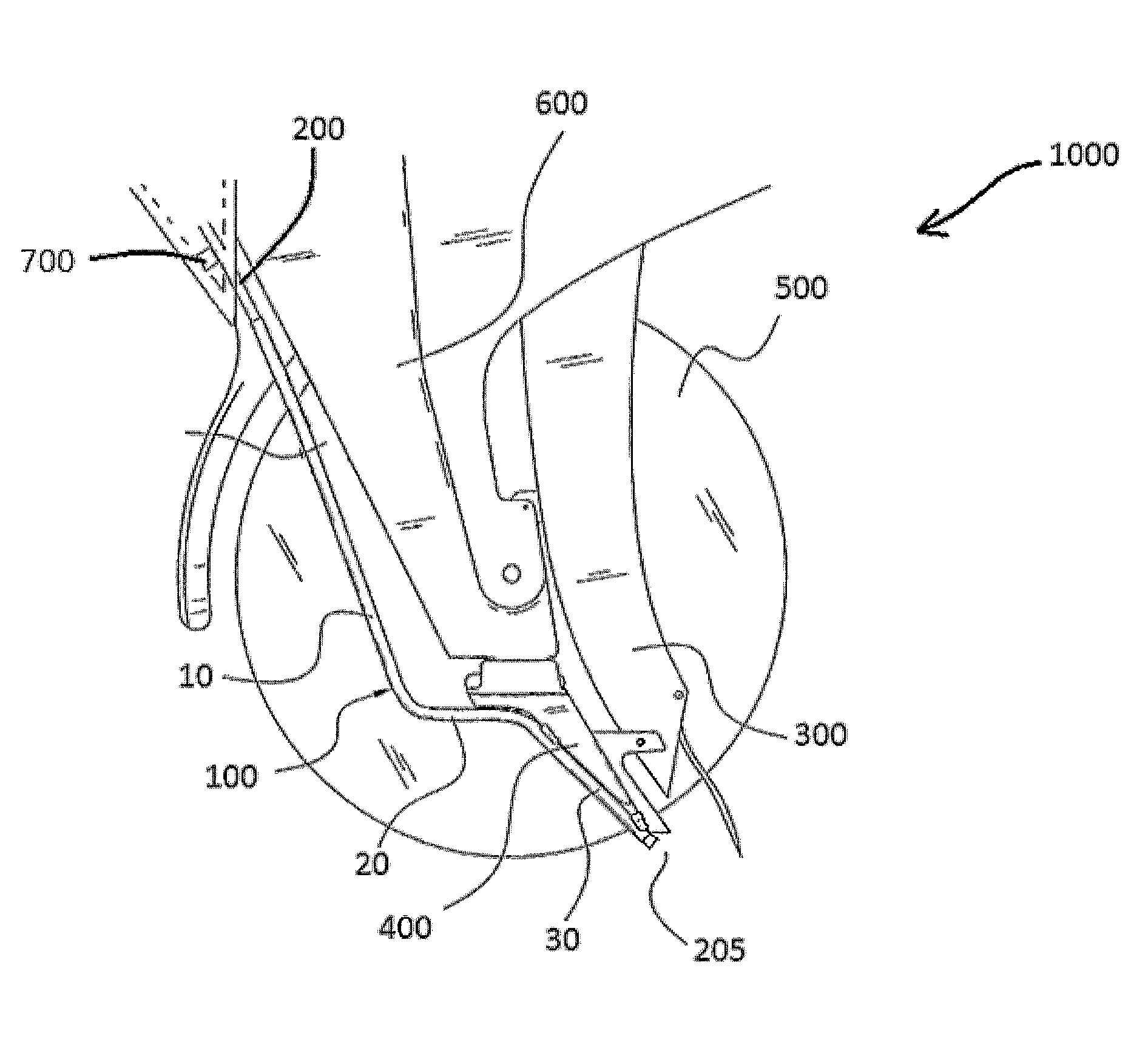
[0018]Example embodiments will now be described more fully with reference to the accompanying drawings, in which example embodiments of the invention are shown. The invention may, however, be embodied in different forms and should not be construed as limited to the embodiments set forth herein. Rather, these embodiments are provided so that this disclosure will be thorough and complete, and will fully convey the scope of the invention to those skilled in the art. In the drawings, the sizes of components may be exaggerated for clarity.

[0019]It will be understood that when an element or layer is referred to as being “on,”“connected to,” or “coupled to” another element or layer, it can be directly on, connected to, or coupled to the other element or layer or intervening elements or layers that may be present. In contrast, when an element is referred to as being “directly on,”“directly connected to,” or “directly coupled to” another element or layer, there are no intervening elements or...


PUM


Abstract

Disclosed is a fertilizer application system that may include a planter implement, a sleeve attached to the planter implement, and a flexible hose extending through at least a portion of the sleeve. In example embodiments the flexible hose may be configured to transport liquid fertilizer from a fertilizer tank to a furrow in a ground created by the planter implement.

Description

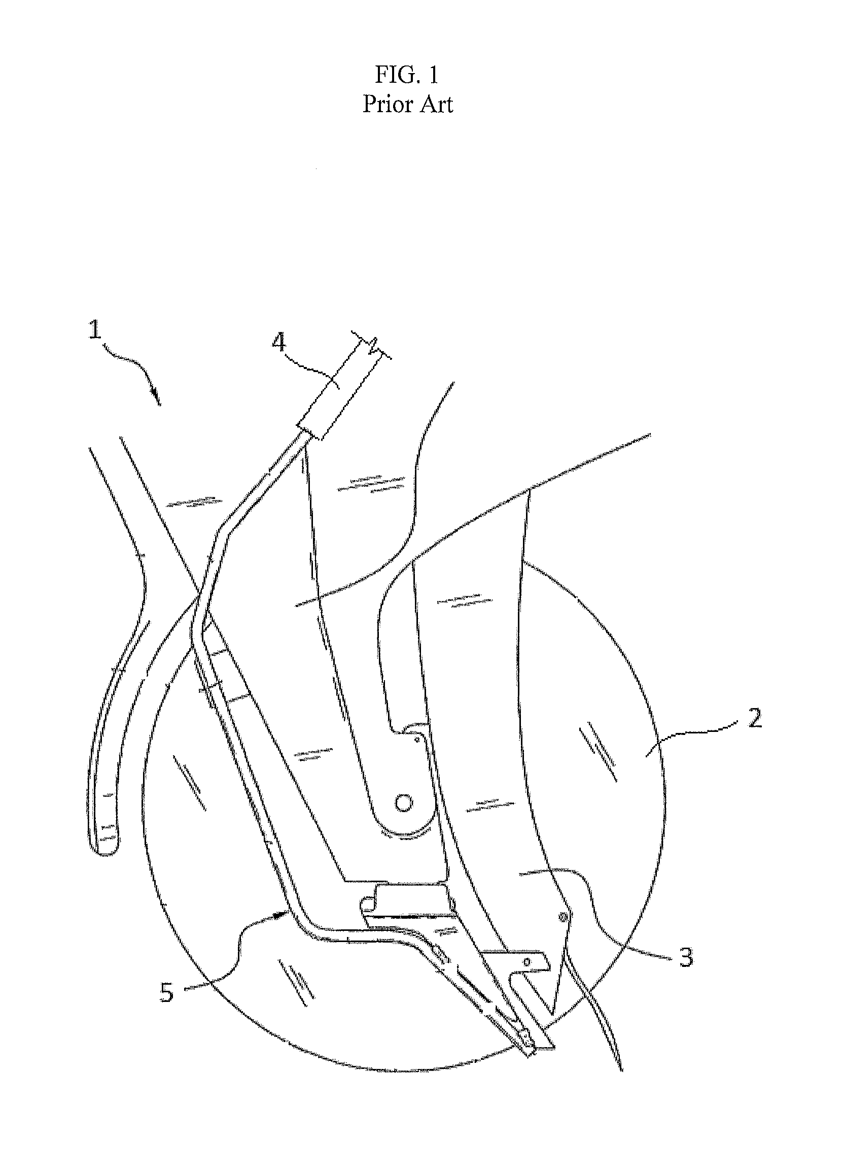
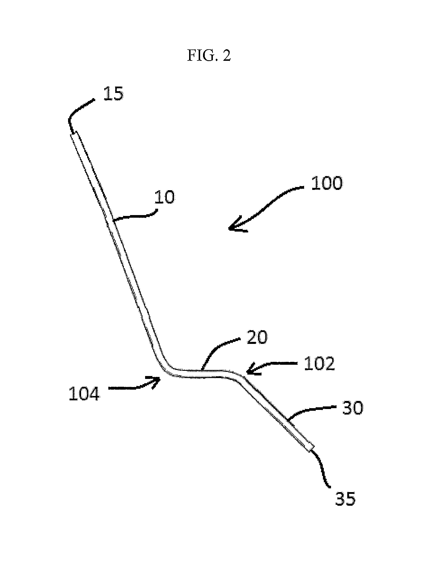
BACKGROUND[0001]1. Field[0002]Example embodiments relate to fertilizer placement tubes and systems that use the fertilizer placement tubes.[0003]2. Description of the Prior Art[0004]FIG. 1 is a view of a conventional liquid fertilizer application system 1. As shown in FIG. 1, the conventional liquid fertilizer application system 1 includes an implement comprised of a pair of disks 2 (only one of which is shown in FIG. 1), a seed tube 3, and a fertilizer hose 4. Generally speaking, the pair of disks 10 are configured to open a furrow in the ground and the fertilizer tube 4 is configured to deposit fertilizer into the furrow via a fertilizer tube 5 which receives liquid fertilizer from the fertilizer tube 4. After the fertilizer is applied to the furrow a seed is deposited in the furrow which is then covered by soil.[0005]In some conventional liquid fertilizer application systems the fertilizer tube 5 is a rigid tube having several bends. In the conventional art the fertilizer hose 4 ...

Claims


Application Information

Patent Timeline
Patent Type & Authority Patents(United States)
IPC IPC(8): A01C23/02A01C7/06A01B49/06
CPCA01C23/025A01C7/06A01B49/06A01C5/064
Inventor NELSON, LARRY
Owner L & D AG SERVICE INC
Why Eureka
Try Eureka