
Digital camera

a digital camera and camera body technology, applied in the field of digital cameras, can solve the problems of broken connection of the rom with the main body of the digital camera, inability to operate the digital camera, so as to increase the efficiency of withdrawal, reduce the cost, and simplify the processing

Inactive Publication Date: 2006-11-02
FUJIFILM CORP
View PDF7 Cites 2 Cited by
  • Summary
  • Abstract
  • Description
  • Claims
  • Application Information

AI Technical Summary

Benefits of technology

[0014] The external packing film in the digital camera of the present invention is structured in such a manner that at least one portion is more easily broken than the other portion in the vicinity of the adhered portion and in the vicinity of the mounting position of the wiring. When such a structure is applied, the connection of the ROM to the digital camera main body can be surely broken.
[0016] Further, the second identifying information in the digital camera of the present invention is read from the ROM after the digital camera is produced, and stored in the identifying information memory section. When such a structure is applied, the control of the first and the second identifying information having a predetermined relationship becomes easy.
[0017] Further, in the digital camera of the present invention, as the second identifying information to be stored, the first identifying information is used. When such a structure is applied, the identifying information stored in the ROM can be arbitrary one, and the collation processing becomes simple.
[0018] Further, the reading of the second identifying information from the ROM in the digital camera of the present invention and the storing into the identifying information memory section are conducted by using a predetermined program, and the program is erased after the storing into the identifying information memory section. When such a structure is applied, the reproduction by using a new ROM chip becomes difficult, and the increase of the withdrawal efficiency can be expected.
[0019] Further, as the ROM in the digital camera of the present invention, an electrically erasable ROM is used, and the reading program of the second identifying information from the ROM, and the storing program into the identifying information memory section are previously stored in the ROM. When such a structure is applied, the program storing memory of the digital camera itself can be structured by a low cost ROM.

Problems solved by technology

When such a structure is applied, because the connection of the ROM with the digital camera main body is broken when the recording medium in which the photographed image information is recorded, is taken out, even when the recording medium is mounted again, the digital camera can not be operated.
In the case where such a structure is applied, when the external packing film is taken off in order to take out the recording medium, the connection of the ROM with the digital camera main body is broken, and the digital camera can not be operated again.
In the case where such a structure is applied, when the photographed image information is taken from the internal memory, the connection of the ROM to the digital camera main body is broken, and the digital camera cannot be operated again.

Method used


Image

  • Digital camera
  • Digital camera
  • Digital camera

Examples


first embodiment

The First Embodiment

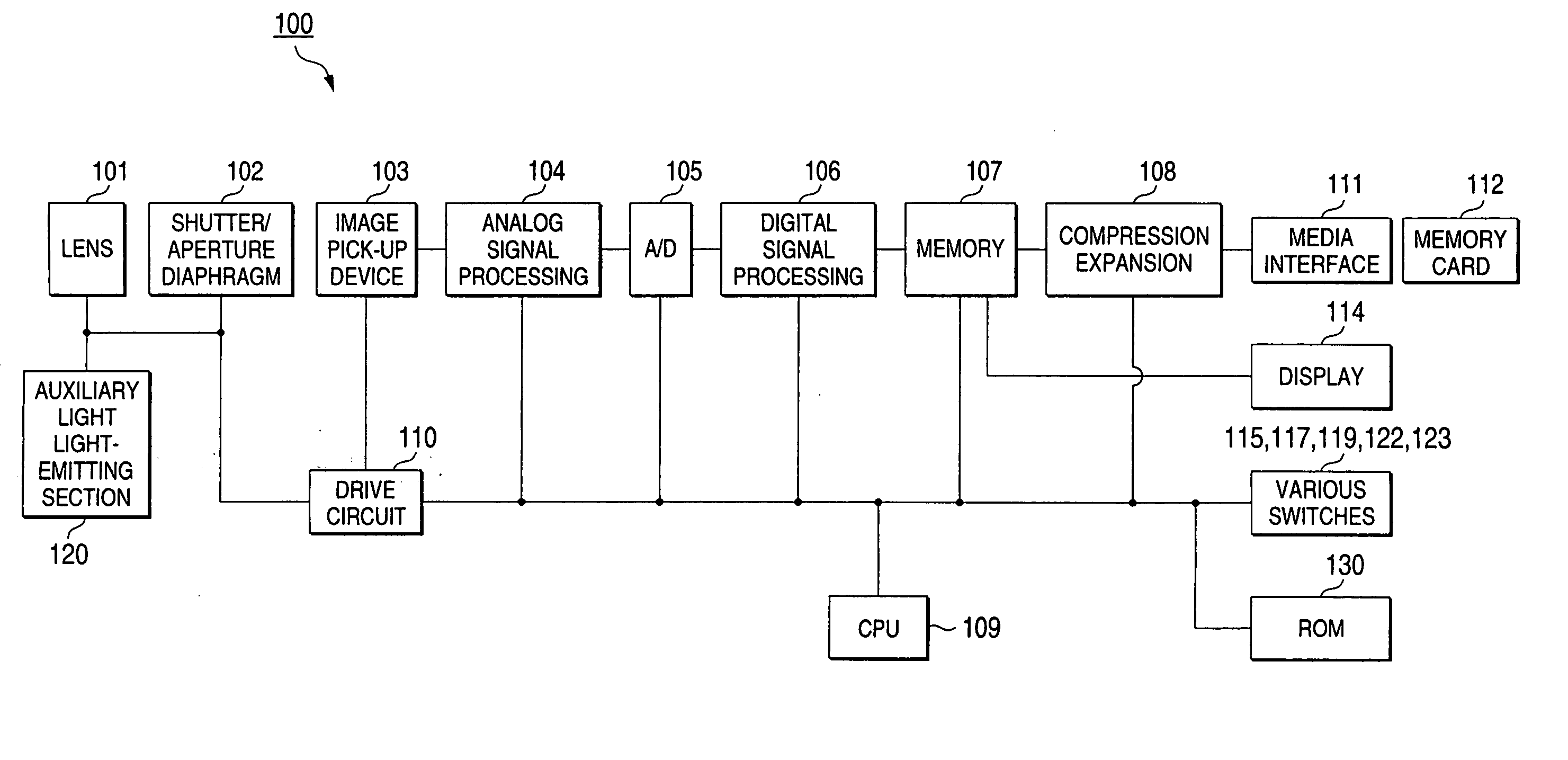
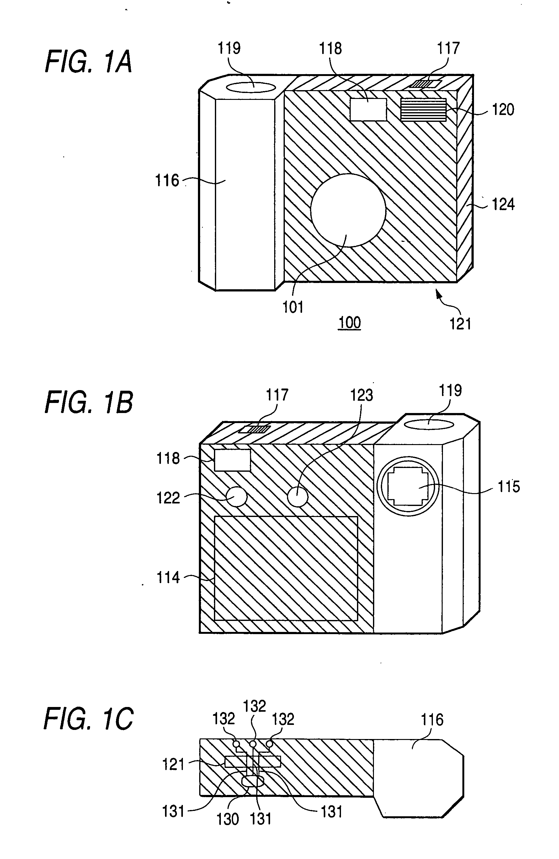
[0029]FIGS. 1A to 1C are appearance general views of a digital camera of the first embodiment, and FIG. 1A shows its front view, FIG. 1B shows its rear surface, and FIG. 1C shows its bottom surface. A digital camera 100 is structured by comprising a casing 116, power switch 117, optical view finder 118, photographing lens 101, shutter button 119, auxiliary light light-emitting section 120, memory card insertion section 121, display 114, operation switch 115, menu switch 122, execution / image plane change over switch 123, external packing film 124, ROM chip 130, print wiring 131, and external connecting terminal 132.

[0030] The external packing film 124 is packed to protect the memory card insertion section 121, and display 114, and to structurally reinforce the main body. The external packing film 124 at least covers the memory card insertion section 121, and when the memory card 112 is taken out after the photographing, it is stripped off. On the one hand, in the...

second embodiment

The Second Embodiment

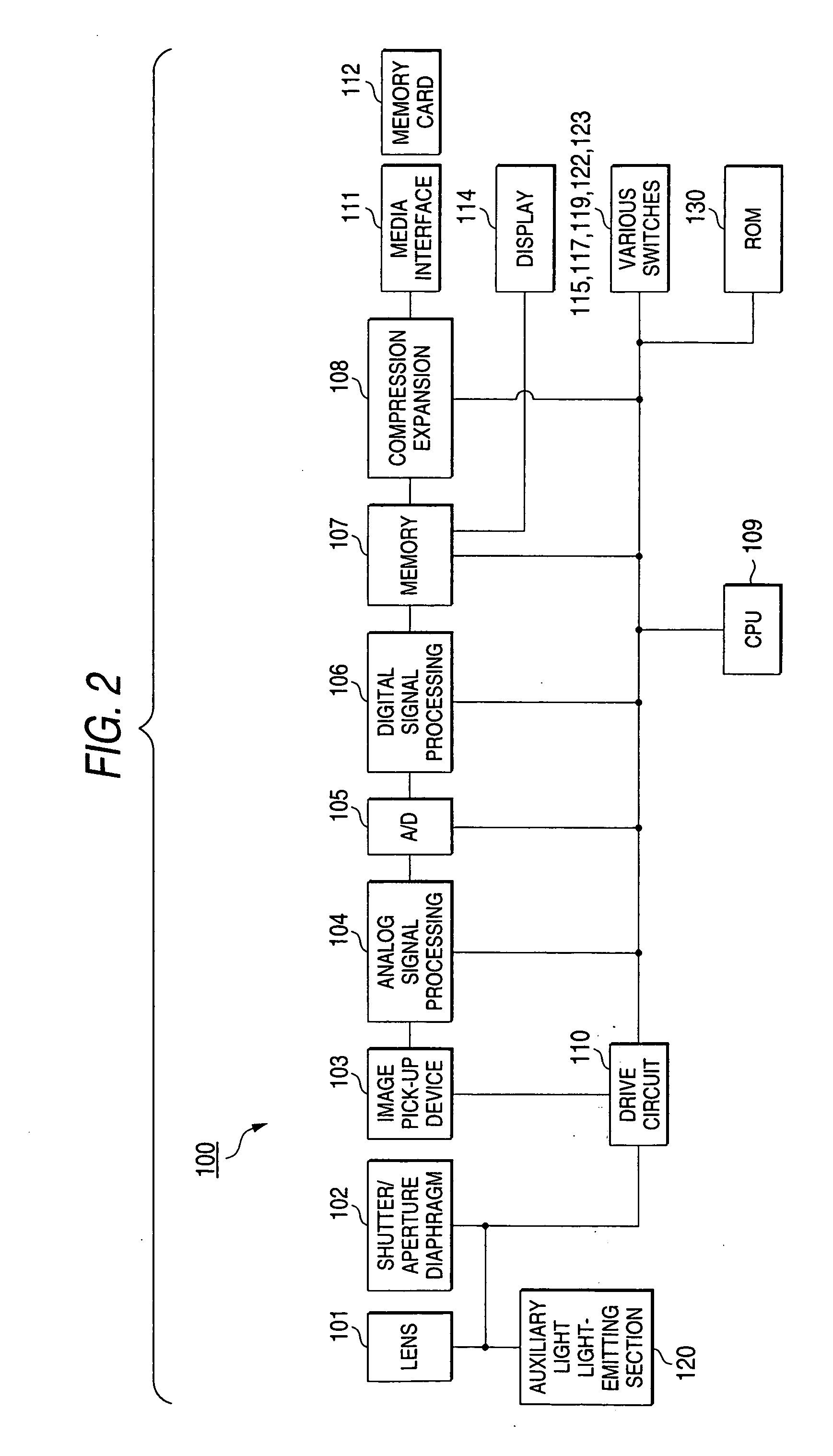
[0052] The digital camera 100 in FIG. 1 is a camera in which the picked up image information is stored in the removable recording medium such as a memory card, however, the digital camera 200 of the second embodiment is a camera in which the picked up image information is stored in the internal memory 113. FIG. 7 shows a bottom surface of the digital camera 200 of the second embodiment, and which is a view corresponding to FIG. 5A. Further, FIG. 8 is an outline block structural view of the digital camera 200.

[0053] The digital camera 200 has basically the same structure and function as the digital camera 100 except a point that the picked up image information is recorded in the internal memory 113 provided in the digital camera 200 inside in place of that it is recorded in the memory card 112 through the media interface 111, and a point that the picked up image information stored in the internal memory 113 is taken out to the outside through the input output in...


PUM


Abstract

On the external packing film 124 of the memory card insertion section vicinity of the bottom surface of the digital camera 100, the ROM chip and the print wiring 131 are surface-mounted, and one end of the print wiring 131 is connected to the ROM chip 130, and the other end is connected to the external connecting terminal 132 provided on the bottom surface of the digital camera 100. The identifying information in the ROM chip 130 is read out at the time of the operation of the digital camera 100, and is collated with the identifying information inside the camera, and when it can not be collated or it is not coincident, the power source of the camera is compulsively turned off.

Description

BACKGROUND OF THE INVENTION [0001] 1. Field of the Invention [0002] The present invention relates to a digital camera, and particularly to a digital camera which is appropriate for an easy use. [0003] 2. Description of the Related Art [0004] At a visit location, when it hurriedly becomes necessary to take a picked up image, there are many cases where a lens-fitted film unit is used. Because a lens-fitted film unit can be easily obtained in a retail shop or an automatic vending machine, even when a camera is not always carried with the person, the desired image can be photographed as necessary, and the recording can be remained. [0005] On the one hand, a digital camera in which the digital image information obtained by an image pick-up element is recorded in a built-in memory or removable recording medium (hereinafter, sometimes simply denoted as “medium”), is widespreadingly used. In such a digital camera, in the same manner as the conventional camera, it has a feature that, not onl...

Claims


Application Information

Patent Timeline
Patent Type & Authority Applications(United States)
IPC IPC(8): H04N5/76G03B19/02G03B17/02H04N1/21H04N5/225H04N5/907H04N5/91H04N101/00
CPCH04N1/0018H04N1/2112H04N1/2158H04N2201/0087H04N2201/0036H04N2201/0084H04N2101/00
Inventor MISAWA, TAKESHI
Owner FUJIFILM CORP
Learn More