Tapered roller bearing

a tapered roller bearing and roller bearing technology, applied in the direction of rolling contact bearings, shafts and bearings, rotary bearings, etc., can solve the problems of large time and effort, strict dimensional control, and large amount of time and effort, so as to reduce the amount of oil flowing, reduce the stirring resistance of oil, and reduce the torque during rotation

Active Publication Date: 2016-08-16
JTEKT CORP
View PDF33 Cites 4 Cited by
  • Summary
  • Abstract
  • Description
  • Claims
  • Application Information

AI Technical Summary

Benefits of technology

[0011]One object of the invention is to provide a tapered roller bearing configured to reduce the amount of oil flowing into a bearing to reduce stirring resistance of the oil, thereby reducing the torque during rotation, without strictly controlling the dimensions of a cage for controlling the dimensions of an outer peripheral clearance.

Problems solved by technology

However, toque loss of the tapered roller bearings is larger than that of ball bearings.
Thus, strict dimensional control that involves a large amount of time and effort is required.

Method used


Image

  • Tapered roller bearing
  • Tapered roller bearing
  • Tapered roller bearing

Examples


Embodiment Construction

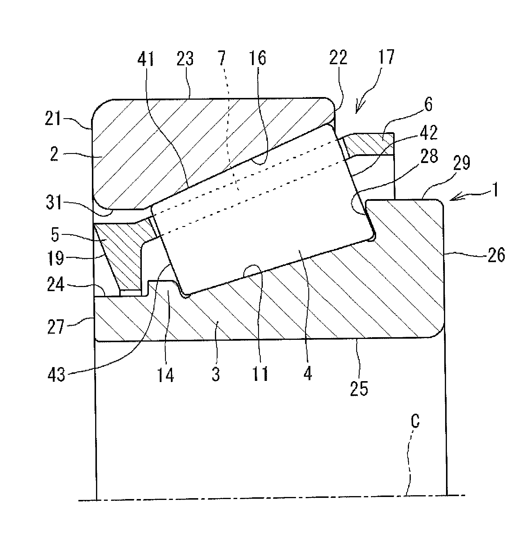
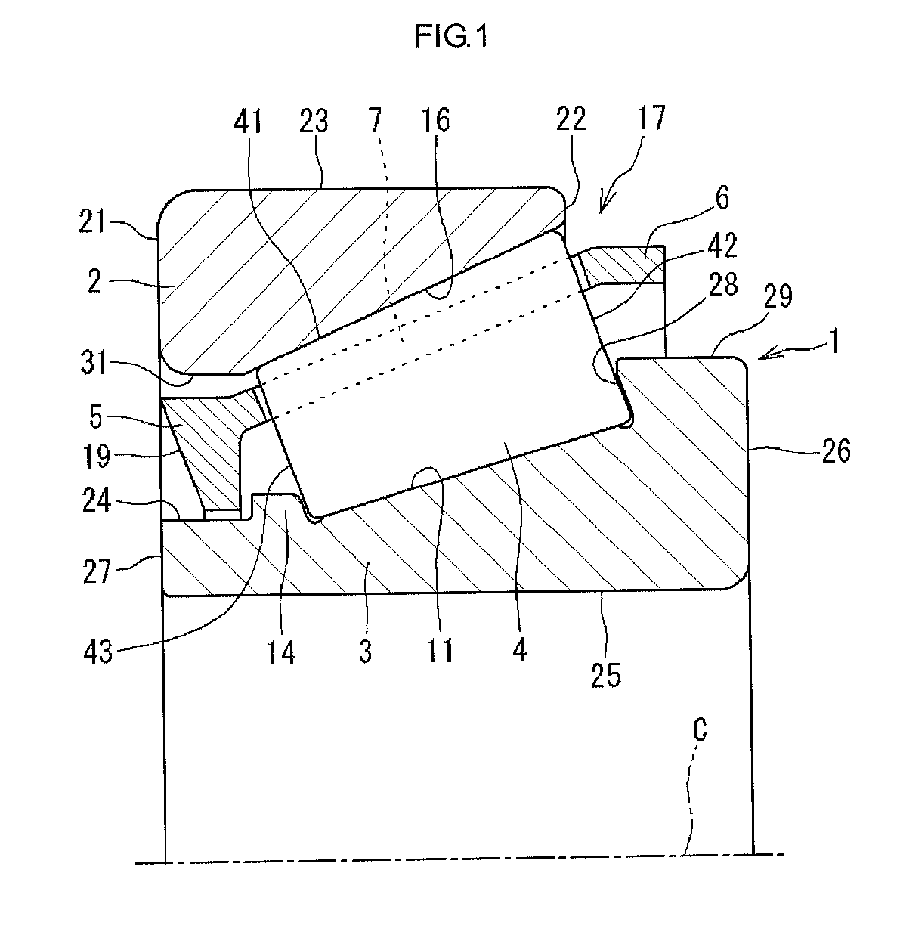
[0027]Hereinafter, an embodiment (first embodiment) of the invention will be described with reference to FIG. 1. A tapered roller bearing 1 illustrated in FIG. 1 is used, for example, to support a pinion shaft of a final reduction gear unit of an automobile. The tapered roller bearing 1 includes an outer ring 2, an inner ring 3, a plurality of tapered rollers 4, and a cage 17 that holds the tapered rollers 4 at equal intervals in the circumferential direction of the tapered roller bearing 1. The outer ring 2 has an outer raceway surface 16 formed on its inner periphery. The inner ring 3 has an inner raceway surface 11 formed on its outer periphery. The tapered rollers 4 are rollably disposed between the outer raceway surface 16 and the inner raceway surface 11. In each embodiment described below, the outer ring 2, the inner ring 3, and the cage 17 have annular (short cylindrical) shapes that share an axis C as a center line.

[0028]The outer ring 2 has an outer peripheral face 23 form...


PUM


Abstract

A corner is formed at a small-diameter-side end portion of a cage. The cage is disposed such that the axial position of a tip of the corner substantially coincides with the axial position of a large end face of an outer ring. Thus, a cylindrical space formed between an inner periphery cylindrical face of the outer ring and an outer periphery cylindrical face of the cage is filled with an oil low pressure region. As a result, the inflow of the oil into a bearing is restricted.

Description

INCORPORATION BY REFERENCE[0001]The disclosure of Japanese Patent Application No. 2013-266844 filed on Dec. 25, 2013 and Japanese Patent Application No. 2014-060337 filed on Mar. 24, 2014, each including the specification, drawings and abstract, is incorporated herein by reference in its entirety.BACKGROUND OF THE INVENTION[0002]1. Field of the Invention[0003]The invention relates generally to a tapered roller bearing, and more specifically to a tapered roller bearing incorporated in, for example, a final reduction gear unit of an automobile and lubricated with oil stored in the final reduction gear unit.[0004]2. Description of the Related Art[0005]FIG. 12 illustrates a conventional tapered roller bearing. The tapered roller bearing includes an outer ring 72, an inner ring 82, a plurality of tapered rollers 74, and a cage 87. The outer ring 72 has an outer raceway surface 71 formed on its inner peripheral face. The inner ring 82 has an inner raceway surface 81 formed on its outer pe...

Claims


Application Information

Patent Timeline
Patent Type & Authority Patents(United States)
IPC IPC(8): F16C33/66F16C19/36F16C33/46
CPCF16C33/6681F16C19/364F16C33/46F16C33/6674F16C33/4635F16C33/4605
Inventor OKAMOTO, DAISUKESUZUKI, AKIYUKI
Owner JTEKT CORP
Why Eureka
Try Eureka