Micromixer assembly for a turbine system and method of distributing an air-fuel mixture to a combustor chamber

a technology of micromixer and turbine system, which is applied in the direction of continuous combustion chamber, combustion process, lighting and heating apparatus, etc., can solve the problems of increasing nox emissions, reducing performance, and affecting the performance of the engin

Active Publication Date: 2016-08-16
GENERAL ELECTRIC CO
View PDF6 Cites 13 Cited by
  • Summary
  • Abstract
  • Description
  • Claims
  • Application Information

AI Technical Summary

Problems solved by technology

Due to upstream conditions, such as the flow experiencing a sharp turn just prior to entering the inlets, non-uniform mass flow often prevails, thereby hindering engine performance.
Decreased performance is a result of ineffective air-fuel mixing prior to injection to the combustor chamber, thereby increasing NOx emissions, for example.

Method used


Image

  • Micromixer assembly for a turbine system and method of distributing an air-fuel mixture to a combustor chamber
  • Micromixer assembly for a turbine system and method of distributing an air-fuel mixture to a combustor chamber
  • Micromixer assembly for a turbine system and method of distributing an air-fuel mixture to a combustor chamber

Examples


Embodiment Construction

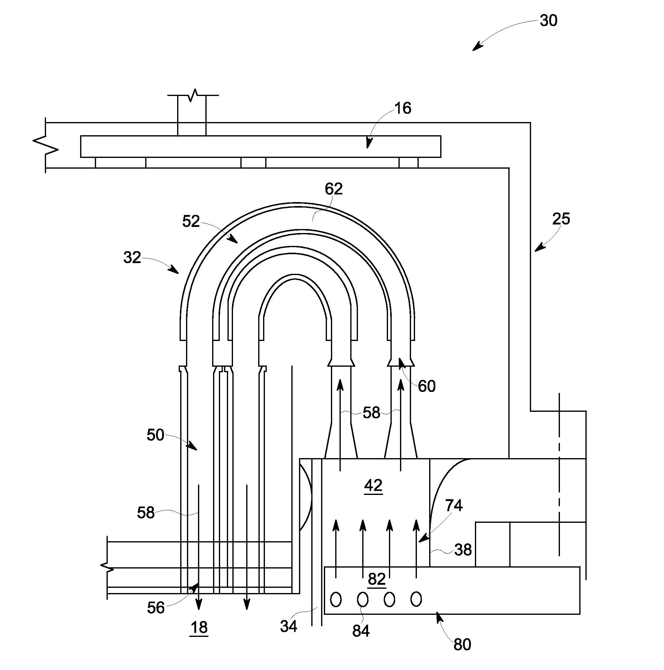
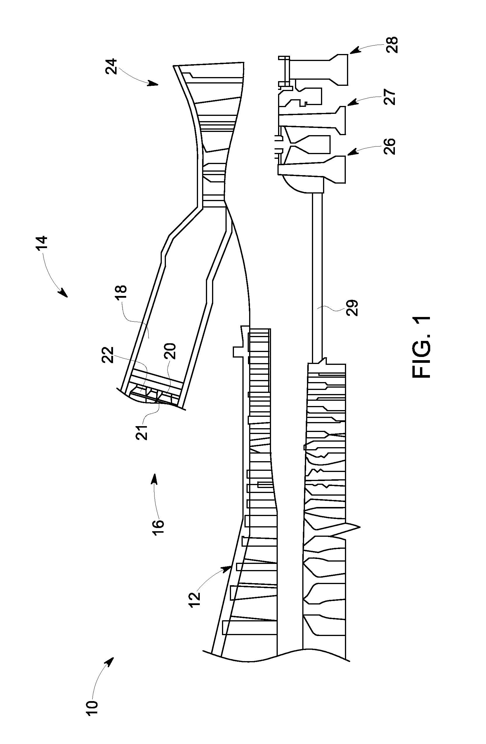
[0018]Referring to FIG. 1, a gas turbine engine 10 constructed in accordance with an exemplary embodiment of the present invention is schematically illustrated. The gas turbine engine 10 includes a compressor 12 and a plurality of combustor assemblies arranged in a can annular array, one of which is indicated at 14. As shown, the combustor assembly 14 includes an endcover assembly 16 that seals, and at least partially defines, a combustor chamber 18. A plurality of tube bundles 20-22 are supported by the endcover assembly 16 and supply fuel to an interior region of the combustor assembly 14. The tube bundles 20-22 receive fuel through a common fuel inlet (not shown) and compressed air from the compressor 12. The fuel and compressed air are passed into the combustor chamber 18 and ignited to form a high temperature, high pressure combustion product or airstream that is used to drive a turbine 24. The turbine 24 includes a plurality of stages 26-28 that are operationally connected to ...


PUM


Abstract

A micromixer assembly for a turbine system includes a plurality of pipes each having an inlet for receiving an airflow from an annulus defined by an inwardly disposed liner and an outwardly disposed sleeve, each of the plurality of pipes also including an outlet for dispersing an air-fuel mixture into a combustor chamber. Also included is a first portion of each of the plurality of pipes. Further included is a second portion of each of the plurality of pipes, the second portion comprising the inlet for receiving the airflow. Yet further included is at least one fuel receiving path in communication with at least one of the first portion and the second portion.

Description

BACKGROUND OF THE INVENTION[0001]The subject matter disclosed herein relates to turbine systems, and more particularly to a micromixer assembly of a gas turbine engine, as well as a method of distributing an air-fuel mixture to a combustor chamber of the gas turbine engine.[0002]Gas turbine systems may include a micromixer, where air distribution to an individual air-fuel pipe should remain at a mean average value of the overall flow. The micromixer typically includes a plurality of pipes or tubes, each having an inlet. Due to upstream conditions, such as the flow experiencing a sharp turn just prior to entering the inlets, non-uniform mass flow often prevails, thereby hindering engine performance. Decreased performance is a result of ineffective air-fuel mixing prior to injection to the combustor chamber, thereby increasing NOx emissions, for example.BRIEF DESCRIPTION OF THE INVENTION[0003]According to one aspect of the invention, a micromixer assembly for a turbine system includes...

Claims


Application Information

Patent Timeline
Patent Type & Authority Patents(United States)
IPC IPC(8): F23R3/28F23R3/46
CPCF23R3/46F23R3/286F23R2900/00018
Inventor MELTON, PATRICK BENEDICTBOARDMAN, GREGORY ALLEN
Owner GENERAL ELECTRIC CO
Why Eureka
Try Eureka