Touch panel and fabrication method thereof

a technology of touch panel and fabrication method, which is applied in the field of touch panel, can solve the problems of poor color mixing performance, poor quality of frame of conventional touch panel fabricated by aforementioned processes, and easy blockage of colored particles in the nozzle used in the fabricating process, etc., and achieves the effect of improving the quality sense of frame and high-variable appearance of touch panel

Active Publication Date: 2016-08-16
WINTEK CORP
View PDF5 Cites 2 Cited by
  • Summary
  • Abstract
  • Description
  • Claims
  • Application Information

AI Technical Summary

Benefits of technology

[0006]It is one of the primary objectives of the present invention to provide a touch panel and a fabrication method thereof, wherein a patterned decoration frame is utilized to improve the quality sense of the frame with the stereoscopic appearance of the touch panel, so as to obtain the high variable appearance of the touch panel.

Problems solved by technology

It is because when the frame of the conventional touch panel is fabricated by using colored particles, which are usually delivered with a carrier, the nozzle used in the fabricating process is easily blocked with those colored particles.
Thus, those colored particles will be distributed non-uniformly, thereby leading to poor color mixing performance.
Moreover, the frame of the conventional touch panel fabricated by aforementioned processes usually has poor optical density (OD), and which is less capable of shielding the metal wire of the touch panel.
Therefore, the conventional touch panel cannot meet the market demands.
It is the reason that the frame of the conventional touch panel has to be limited in dark colors or monochromatic appearance.

Method used


Image

  • Touch panel and fabrication method thereof
  • Touch panel and fabrication method thereof
  • Touch panel and fabrication method thereof

Examples


Embodiment Construction

[0019]To provide a better understanding of the present invention to those skilled in the art of the present invention, preferred embodiments are detailed as follows. The preferred embodiments of the present invention are illustrated in accordance with the accompanying figures to detail describe the contents and effects to be achieved.

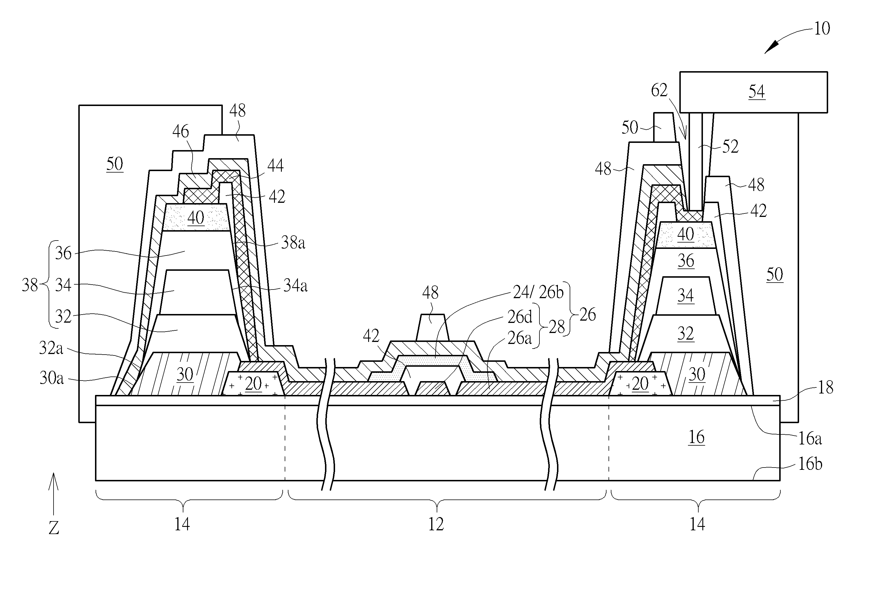
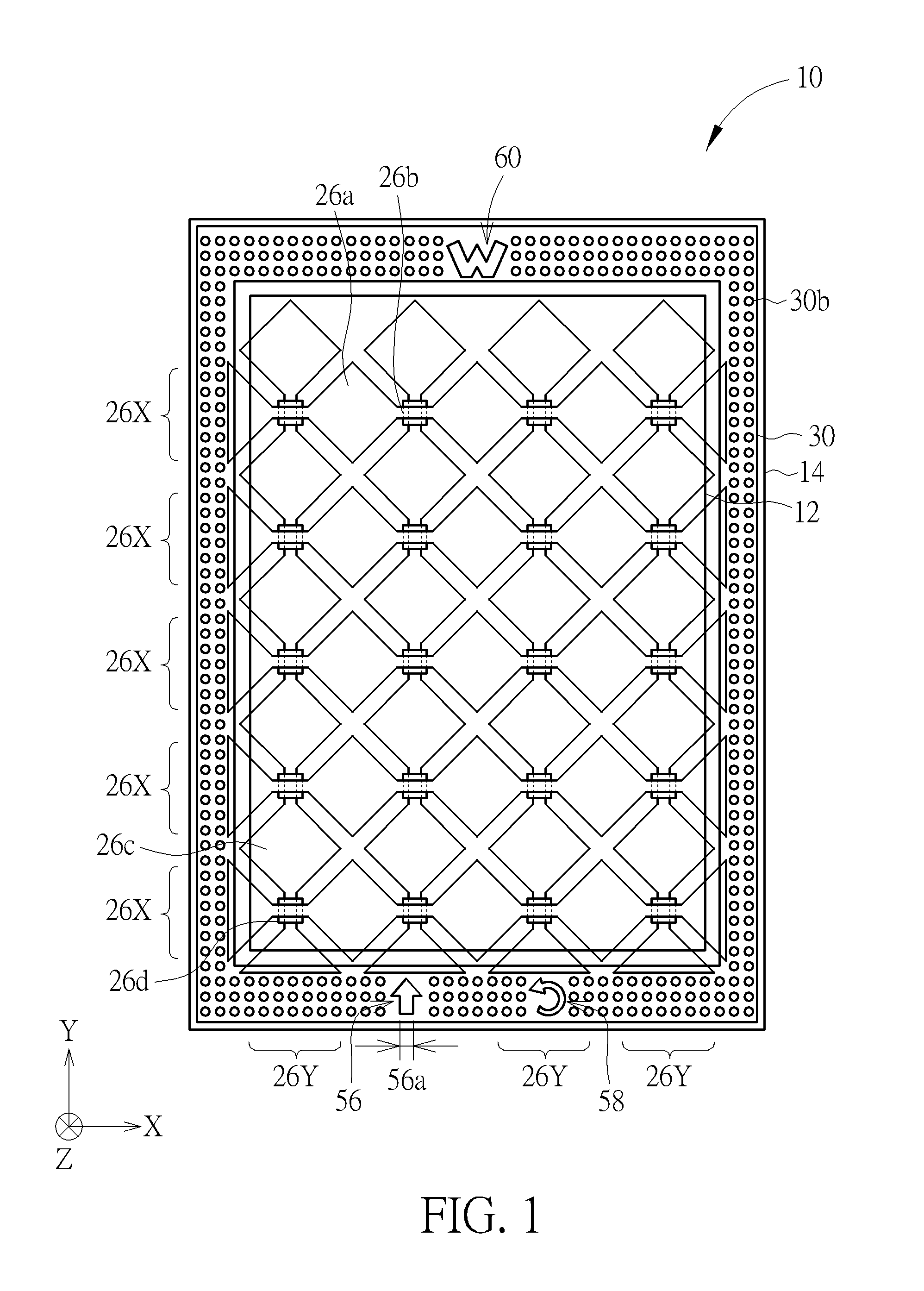
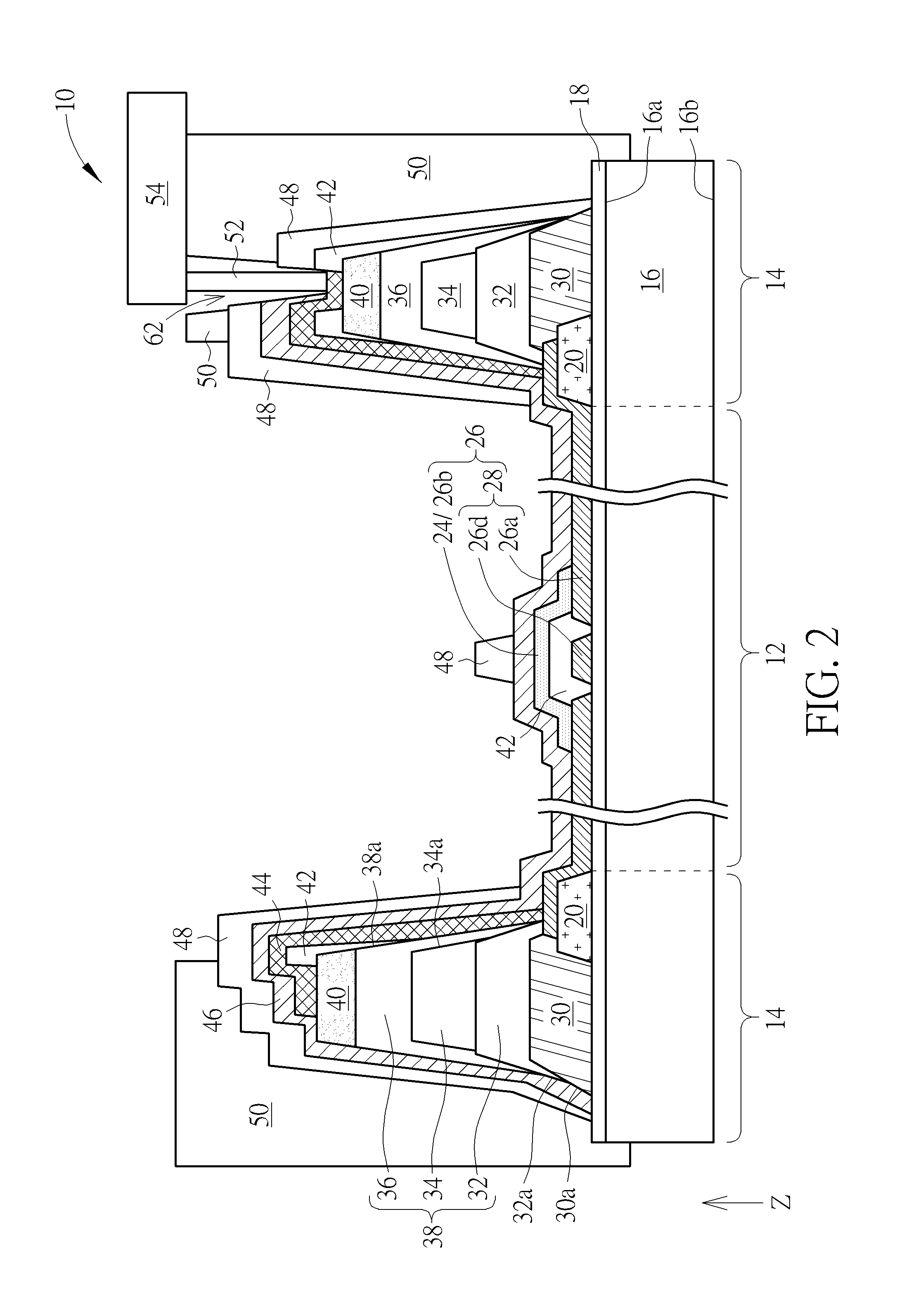
[0020]Referring to FIG. 1 and FIG. 2, FIG. 1 is a schematic top view illustrating a touch panel according to a first embodiment of the present invention, and FIG. 2 is a cross-sectional schematic view of a portion of the touch panel according to the first embodiment of the present invention. In order to simply present the main features of the present invention, only a part of elements in the touch panel are illustrated in FIG. 1. As shown in FIG. 1 and FIG. 2, a touch panel 10 of the present invention has a light transmission touch sensing region 12 and a peripheral region 14. The peripheral region 14 is disposed adjacent to at least one side of the lig...


PUM


Abstract

The present invention discloses a touch panel, having a light transmission touch sensing region and a peripheral region adjacent to at least one side of the light transmission touch sensing region. The touch panel includes a substrate, a patterned decoration frame, a decoration layer, and at least one touch sensing element. The patterned decoration frame is disposed on a surface of the substrate and in the peripheral region. The decoration layer is disposed on the patterned decoration frame, and the touch sensing element is disposed in the light transmission touch sensing region.

Description

BACKGROUND OF THE INVENTION[0001]1. Field of the Invention[0002]The present invention relates to a touch panel and a fabrication method thereof, and more particular, to a touch panel having a stereoscopic frame and a fabrication method thereof.[0003]2. Description of the Prior Art[0004]Touch panel has been widely used in various electronic products, including smart phones, GPS navigator systems, tablet PCs, personal digital assistants (PDA), and laptop PCs, due to the human-machine interaction property thereof.[0005]Conventional touch panel usually has monochromatic frame on its surface, which lacks stereoscopic appearance and variability. It is because when the frame of the conventional touch panel is fabricated by using colored particles, which are usually delivered with a carrier, the nozzle used in the fabricating process is easily blocked with those colored particles. Thus, those colored particles will be distributed non-uniformly, thereby leading to poor color mixing performan...

Claims


Application Information

Patent Timeline
Patent Type & Authority Patents(United States)
IPC IPC(8): G06F3/041
CPCG06F3/041G06F3/04164G06F2203/04103
Inventor LIN, YI-CHUNHUANG, SIANG-LINSU, KUO-CHANG
Owner WINTEK CORP
Why Eureka
Try Eureka