Power cable joint manufacturing quality detection device and method
A technology of power cables and testing equipment, which is applied in the field of testing equipment for the production quality of power cable joints, can solve problems such as cable faults, and achieve the effects of anti-counterfeiting of detection data, convenient management of detection data, and traceability of cable head faults
- Summary
- Abstract
- Description
- Claims
- Application Information
AI Technical Summary
Problems solved by technology
Method used
Image
Examples
Embodiment 1
[0061] This embodiment takes the integrated structure of the control mechanism and the detection device as an example to describe the following.
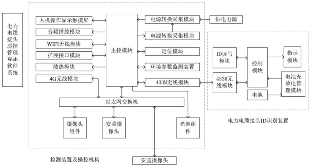
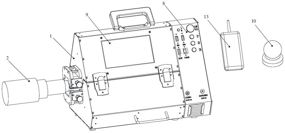
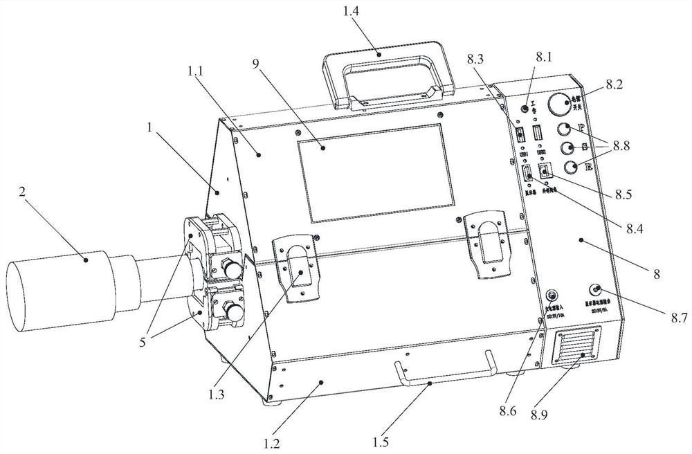
[0062] like Figure 1 to Figure 11 As shown, the detection equipment for the production quality of the power cable joint of the present invention includes:
[0063] The detection device is used to collect images or videos of the power cable connector 2 through machine vision technology;
[0064] The environmental parameter monitoring device is used to monitor the production environment of the power cable joint 2;
[0065] A power cable joint ID identification device 13, used for automatic identification of the power cable joint ID;
[0066] And the control mechanism, which is used to obtain the collected images or videos, the monitored environmental parameters and the data identified by the power cable connector ID, and perform processing, calculation, statistical analysis and storage, and finally obtain the test results and gener...
Embodiment 2
[0094] This embodiment differs from Embodiment 1 only in that: Figure 12 As shown, the control mechanism and the detection device in this embodiment have a split structure, and the control mechanism and the detection device are connected by signal. The detection box of the detection device in this embodiment is not equipped with a touch screen for man-machine operation and display.
[0095] like Figure 13 As shown, the control mechanism 14 of this embodiment includes a main box body 14.1 and a cover 14.2 hinged with the main box body 14.1, wherein the cover 14.2 is provided with a display screen 14.3, a speaker 14.4, a keypad, and a display input source HDMI extension Mouth and the hasp piece one 14.5 that covers and locks with main casing 14.1. The face cover 14.2 and the main box body 14.1 are connected by the face cover and the main box body connecting rod and the in-line damping rotating shaft 14.6, and the line passing protection cover 14.7 is used to realize wiring be...
Embodiment 3
[0100] The only difference between this embodiment and Embodiment 1 is that the machine vision acquisition units of this embodiment can be set to 4, 5 and 6 according to the requirements of shooting or acquisition angles, among which the camera assembly 3 and the light source assembly 4 are distributed as Figure 17 , Figure 18 and Figure 19 as shown, Figure 17 , Figure 18 and Figure 19 The light source assembly 4 only shows the LED light bar.
[0101] Other structures of this embodiment are consistent with Embodiment 1.
PUM
 Abstract
Description
Claims
Application Information
 - R&D
- Intellectual Property
- Life Sciences
- Materials
- Tech Scout
- Unparalleled Data Quality
- Higher Quality Content
- 60% Fewer Hallucinations
Browse by: Latest US Patents, China's latest patents, Technical Efficacy Thesaurus, Application Domain, Technology Topic, Popular Technical Reports.
© 2025 PatSnap. All rights reserved.Legal|Privacy policy|Modern Slavery Act Transparency Statement|Sitemap|About US| Contact US: help@patsnap.com


