Systems and methods for conditioning a filter assembly

Active Publication Date: 2016-08-23
PALL CORP
View PDF16 Cites 0 Cited by
  • Summary
  • Abstract
  • Description
  • Claims
  • Application Information

AI Technical Summary

Benefits of technology

[0006]Methods and systems embodying these aspects of the invention have many advantageous features, including, for example, features that are highly effective for removing any contaminants from the filter assembly before the filter assembly is used to filter any chemicals. For example, by filling the filter assembly, including the upstream side of the filter medium, the filter medium itself, and the downstream side of the filter mediums, with purging liquid, methods and systems embodying the invention ensure that the filter assembly is thoroughly flushed by the purging liquid. Contaminants, including gas such as air, in the interior of the filter assembly are displaced and / or carried away by the purging liquid, leaving the filter assembly largely free of contaminants. Further, by applying a vacuum to the open outlet while the inlet is closed, any remaining contaminants, especially any gas trapped in the pores and voids of the filter medium or entrained in the purging liquid, are quickly and effectively removed via the open outlet by the vacuum. For many embodiments, both the outlet and the vent may be opened while the inlet is closed, and the vacuum device may apply the vacuum to both the open outlet and the open vent to even more quickly and effectively remove any remaining gas in the filter assembly.
[0008]Methods embodying this aspect of the invention also have several advantageous features. For example, by passing the purging liquid from the waste reservoir into the second assembly, the purging liquid waste may be neatly and safely contained within the second assembly. The inlet, outlet, and vent of the second assembly may be sealed, and the sealed second assembly containing the purging liquid waste may be appropriately disposed of, e.g., incinerated, without exposing either the environment or any service personnel to any hazardous substances.

Problems solved by technology

As the filter assembly is flushed, the purging liquid may displace any gas within the filter assembly and carry away any gas and other contaminants contained in the filter assembly.

Method used


Image

  • Systems and methods for conditioning a filter assembly
  • Systems and methods for conditioning a filter assembly
  • Systems and methods for conditioning a filter assembly

Examples


Embodiment Construction

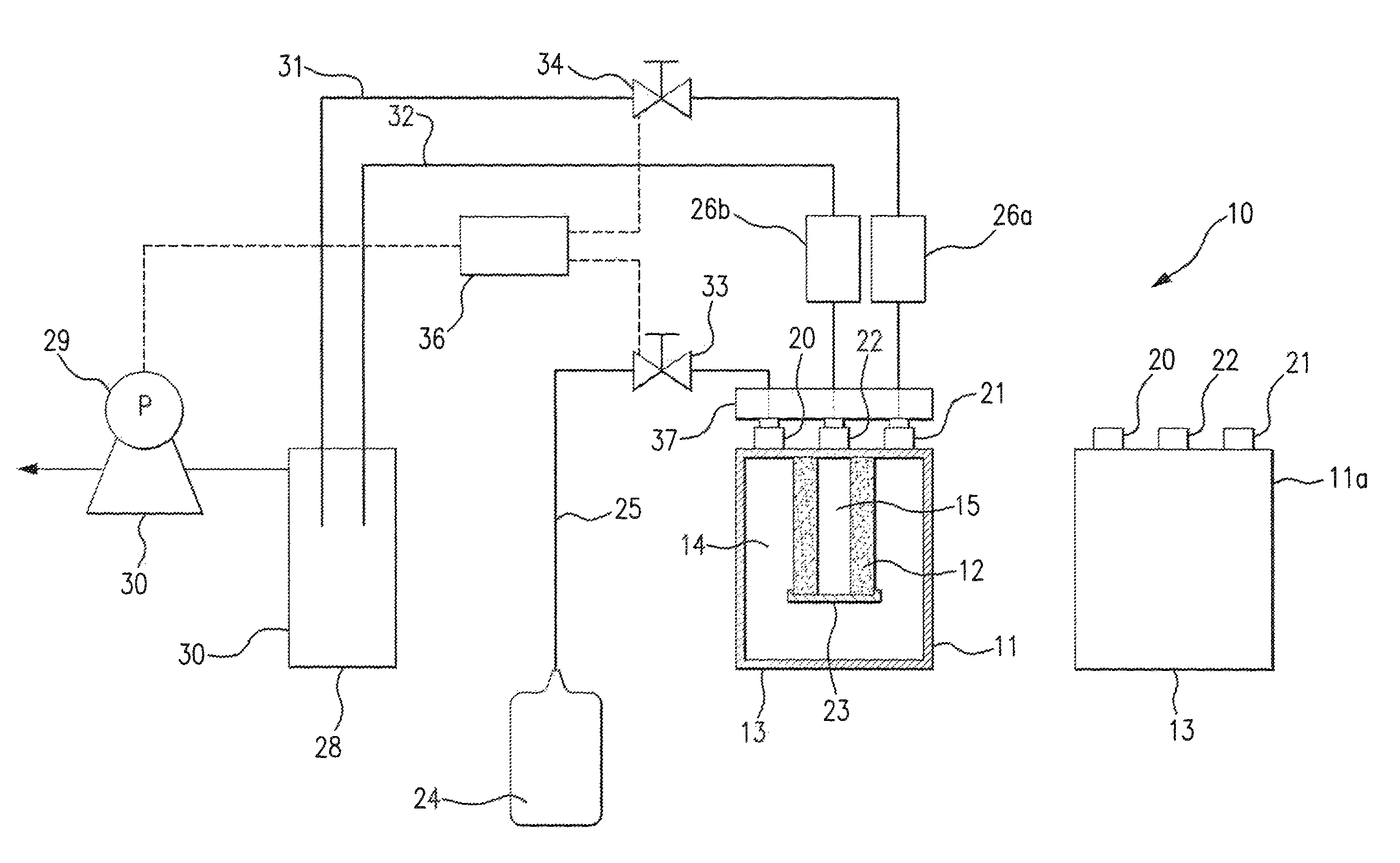
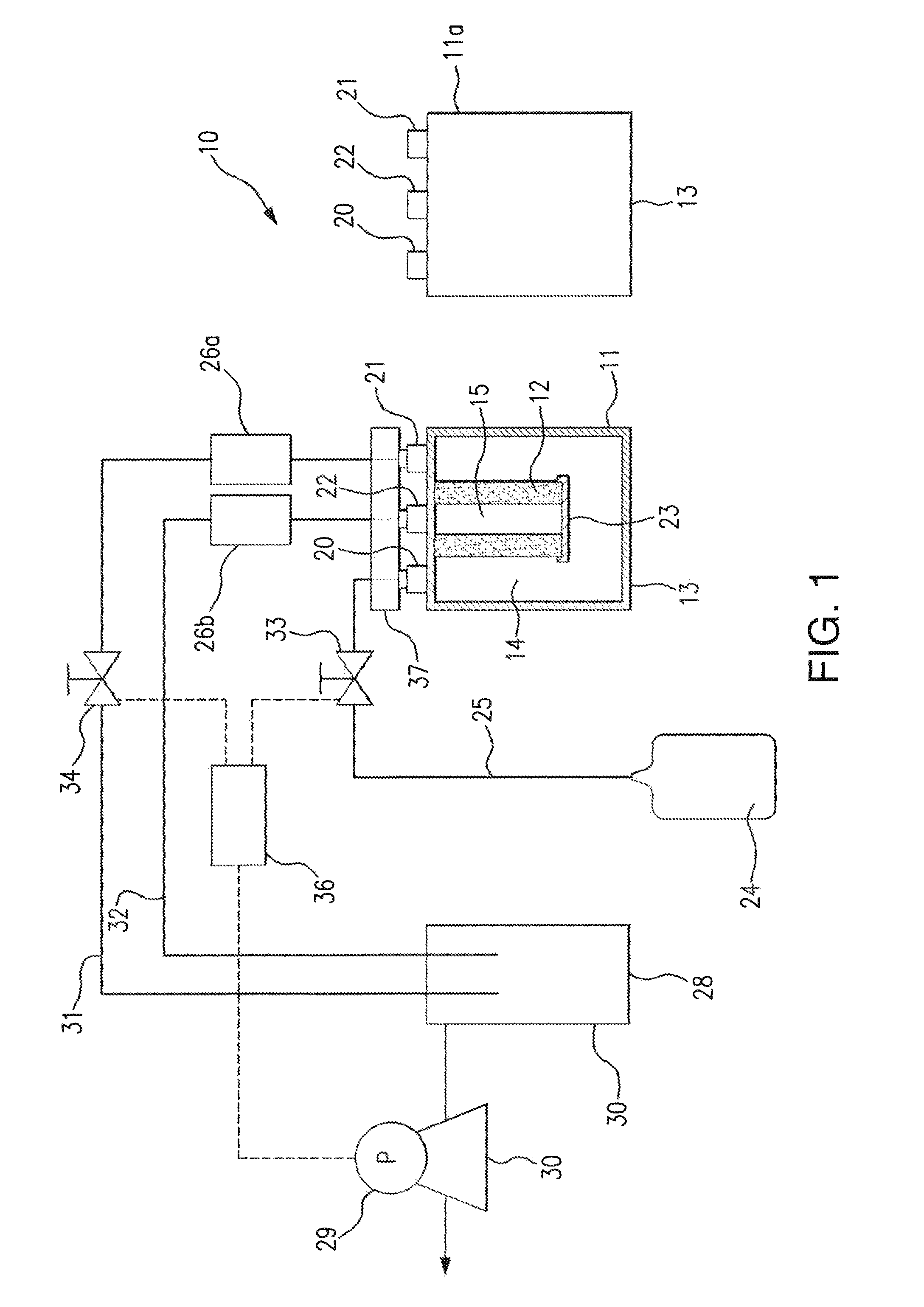
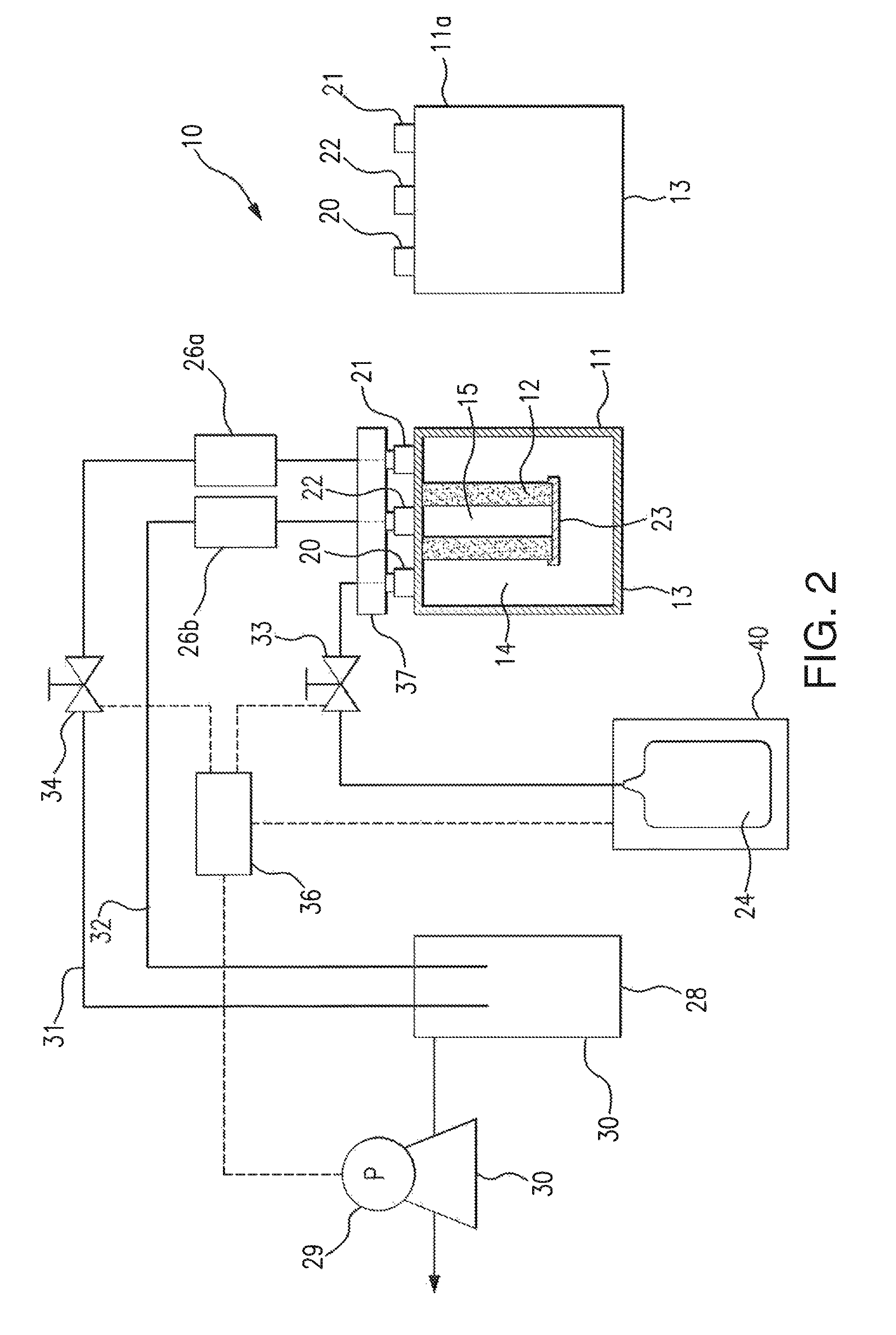
[0011]Systems for conditioning filter assemblies in accordance with one or more aspects of the invention may be embodied in any of numerous ways and may be used to condition any of a great variety of filter assemblies, either one filter assembly at a time or a plurality of filter assemblies all at once.

[0012]Each filter assembly may be variously configured. As shown in FIG. 1, each filter assembly 11 may include a filter medium 12 for removing contaminants from a liquid chemical used in an industrial process. For many of these industries, e.g., the microelectronics industry and the pharmaceutical industry, the chemical must be extremely pure. Consequently, the filter medium may have a removal rating in the microporous or nanoporous range. For example, the removal rating may be down to about 0.05 microns or less than 0.05 microns, including about 40, 30, 20, 10, or 5 nanometers or less. The filter may, for example, be formed from a permeable metallic material, a permeable ceramic mat...


PUM

PropertyMeasurementUnit
total volumeaaaaaaaaaa
flow rateaaaaaaaaaa
vacuumaaaaaaaaaa

Abstract

Systems and methods condition a filter assembly. Purging liquid is passed through the filter assembly to remove contaminants from the pores and voids of the filter medium and from the upstream and downstream sides of the filter medium.

Description

DISCLOSURE OF THE INVENTION[0001]The chemicals used in many industries, including the microelectronics industry and the pharmaceutical industry, must be extremely pure. Very fine filtration of these chemicals is required, often at the point of use, to remove any contaminants that might disrupt the processes used, or ruin the products made, by these industries. Generally, the filter assemblies used to filter these chemicals have a permeable filter medium. The chemical will pass through the filter medium, and any contaminants in the chemical will be trapped within or on the surface of the filter medium.[0002]Before a chemical is filtered, systems and methods embodying the invention condition the filter assembly and prevent the filter assembly itself from introducing contaminants into the chemical. Generally, a purging liquid is flushed through the filter assembly to remove any contaminants that might be contained within the filter assembly, even a newly manufactured filter assembly. T...

Claims


Application Information

Patent Timeline
Patent Type & Authority Patents(United States)
IPC IPC(8): B01D65/02B01D41/04A61M1/16
CPCB01D65/02B01D41/04B01D29/62B01D35/22B01D37/00B01D65/027
Inventor SAKAMOTO, ATSUSHIKATAOKA, HISAYUKIMIZUNO, TAKEHITOTSUTSUMI, KAZUMA
Owner PALL CORP
Why Eureka
Try Eureka