Bolt shear force sensor

Active Publication Date: 2016-08-30
UNITED STATES OF AMERICA
View PDF36 Cites 24 Cited by
  • Summary
  • Abstract
  • Description
  • Claims
  • Application Information

AI Technical Summary

Benefits of technology

[0024]The present invention provides a device capable of continuous and real-time monitoring of shear forces in fasteners used in mechanical joints. The sensor can be used in both static and dynami

Problems solved by technology

While it is well known that structures typically fail at mechanical joints and other discontinuities; there are significant difficulties in assessing and predicting localized distribution of forces within the mechanical fasteners used at the joints.
These difficulties increase when loading forces are dynamic as in the case of shock, blast, vibration and seismic events.
As such, making a determination of proper sizing, spacing, pre-tensioning and quality of fasteners becomes increasingly critical.
However, these devices and methods do not adequately measure fas

Method used


Image

  • Bolt shear force sensor
  • Bolt shear force sensor
  • Bolt shear force sensor

Examples


Embodiment Construction

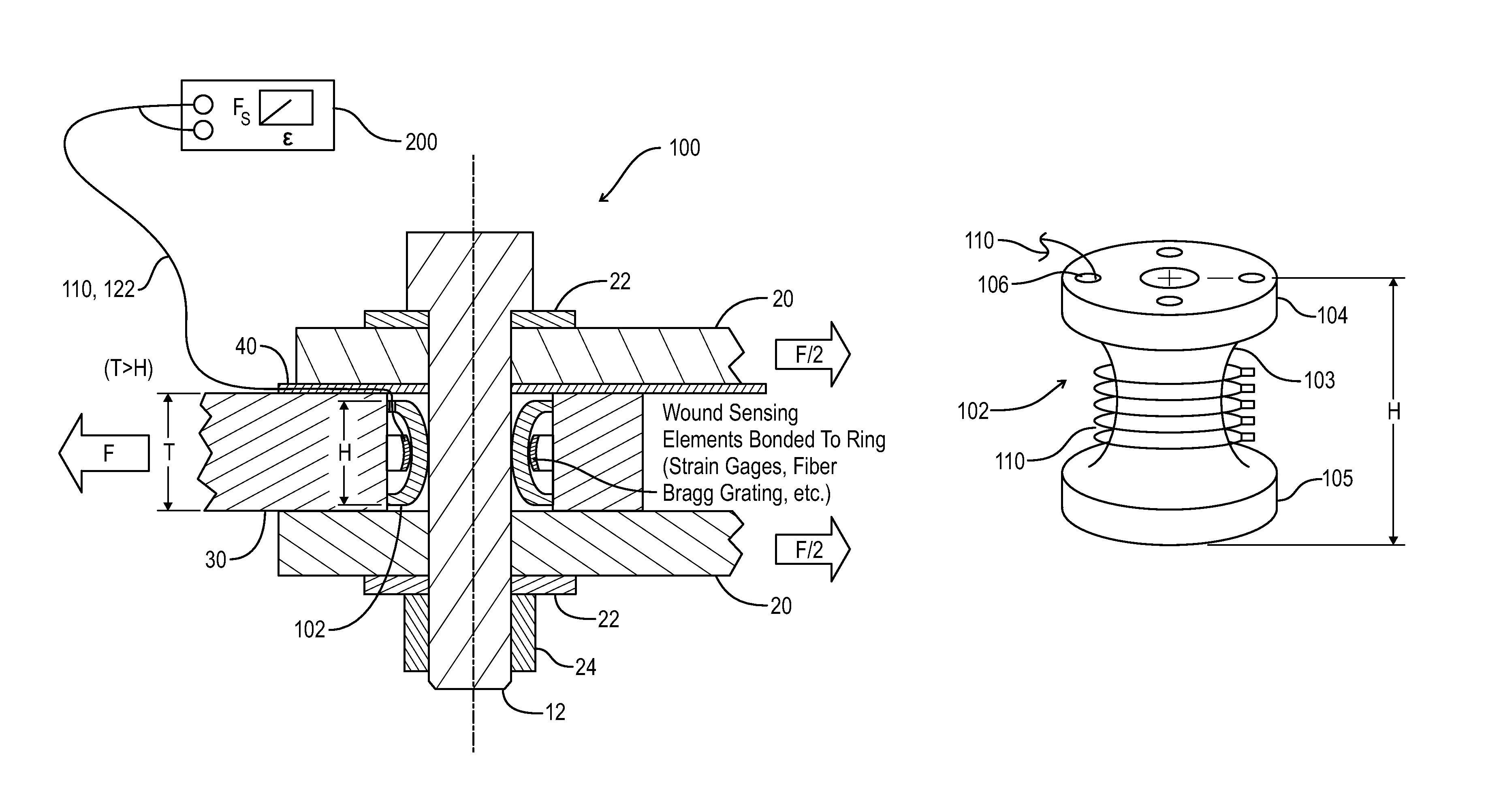
[0039]As depicted in FIG. 6, the present invention provides a bolt shear force sensor 100 having a nearly-rigid, yet deformable ring 102 with indented channel-like cross-sections. In the figure, a bolt 12 is positioned between plates 20 and secured with washers 22 and a nut 24. Forces acting on the bolt 12 and the deformable ring 102 are depicted by direction arrows “F” and “F / 2”.

[0040]As shown in the detail view of FIG. 7, the deformable ring 102 is a shear force sensor ring employing an optical fiber 110. The optical fiber 110 is continuously wound around and glues (fastened) to a vertical section 103 positioned between an upper flange 104 and a lower flange 105 of the ring 102. The optical fiber 110 includes Bragg gratings which are commonly used as measuring sensors.

[0041]The deformable ring 102 includes at least one egress hole or aperture 106 which provides a conduit for the optical fiber 110 to connect to a signal conditioner 200 (See FIG. 6). The deformable ring 102 may be c...


PUM


Abstract

A bolt shear force sensor for in-service monitoring is provided in which the sensor includes a deformable ring with channel-like cross-sections and a wire egress hole. The ring surrounds a bolt or fastener to be tested. The channel-like cross sections face exterior to a center of the ring. Strain sensing elements are mounted within the channel cross-sections as an outer circumference of the ring. The sensing elements capture hoop strain from surrounding plates of the operating system which holds the fastener. A signal conditioner operationally connected via wire conductors is used to convert strain sensing signals from the sensing elements to strain output. The strain outputs are then used in conjunction with a calibration curve of shear force versus strain to determine the magnitudes and directions of the resultant shear forces.

Description

STATEMENT OF GOVERNMENT INTEREST[0001]The invention described herein may be manufactured and used by or for the Government of the United States of America for governmental purposes without the payment of any royalties thereon or therefor.CROSS REFERENCE TO OTHER PATENT APPLICATIONS[0002]None.BACKGROUND OF THE INVENTION[0003](1) Field of the Invention[0004]The present invention relates to a bolt shear force sensor for use in design testing as well as in-service monitoring in order to provide a structural assessment of a bolt or fastener while attached in an operating system.[0005](2) Description of the Prior Art[0006]The design of submarine and ship systems required to survive the effects of mechanical shock must consider not only the system and foundation to which the system is attached but also the mechanical fasteners connecting them. While it is well known that structures typically fail at mechanical joints and other discontinuities; there are significant difficulties in assessin...

Claims


Application Information

Patent Timeline
IPC IPC(8): G01L1/00G01L1/04G01L5/24G01L1/16
CPCG01L1/04G01L1/16G01L5/24G01L1/2237G01L5/166G01L5/243G01L5/1627
Inventor CAVALLARO, PAUL V.
Owner UNITED STATES OF AMERICA
Why Eureka
Try Eureka