
Autonomously landing an unmanned aerial vehicle

an unmanned aerial vehicle and autonomous technology, applied in vehicle position/course/altitude control, process and machine control, instruments, etc., can solve the problems of high cost of both options, no cost-effective process to obtain real-time or near, and no option to provide real-time or near cost-effective process

Active Publication Date: 2016-08-30
SKYCATCH
View PDF9 Cites 50 Cited by
  • Summary
  • Abstract
  • Description
  • Claims
  • Application Information

AI Technical Summary

Benefits of technology

The patent describes systems and methods that enable drones to land autonomously using optical guidance and energy waves. The technological effect is to enable drones to safely land in a safe and efficient manner. Additionally, the systems provide a fine-tuned landing sequence for drones as they descent to the ground station. Overall, the patent helps to improve the efficiency and safety of drone landings.

Problems solved by technology

Both of these options are very costly, and neither option provides a cost-effective process to obtain real-time or near real-time imagery.
This becomes problematic, however, when the UAV is deployed over harsh terrain (e.g., mountains) or over large areas of land.
In such cases, an operator would have difficulty finding a control position (e.g., the physical location of the operator) to allow the operator to successfully control the UAV.
For instance, mountains or large areas of land will generally not allow an operator to maintain the UAV within a viewing range to successfully operate the UAV.
In a long-range remote control scenario, however, additional problems arise with conventional UAVs and conventional UAV systems.
The remote landing process for an operator, however, is often difficult and error-prone, which increases the probability of damaging or destroying a UAV, resulting in considerable expense.
In addition, a damaged UAV can delay a project, causing additional time and expense.
Frequently, however, an operator requires extensive training and practice to be able to successfully remotely land a UAV on a consistent basis.
The time and expense required to train an operator to perform remote UAV landings is cost prohibitive to many companies that would benefit from the use of a UAV.
Moreover, even when adequately trained, an operator still has a fairly high risk of damaging or destroying a UAV during a remote UAV landing.
Thus, there are several disadvantages to current methods for operating and landing a UAV.

Method used


Image

  • Autonomously landing an unmanned aerial vehicle
  • Autonomously landing an unmanned aerial vehicle
  • Autonomously landing an unmanned aerial vehicle

Examples


Embodiment Construction

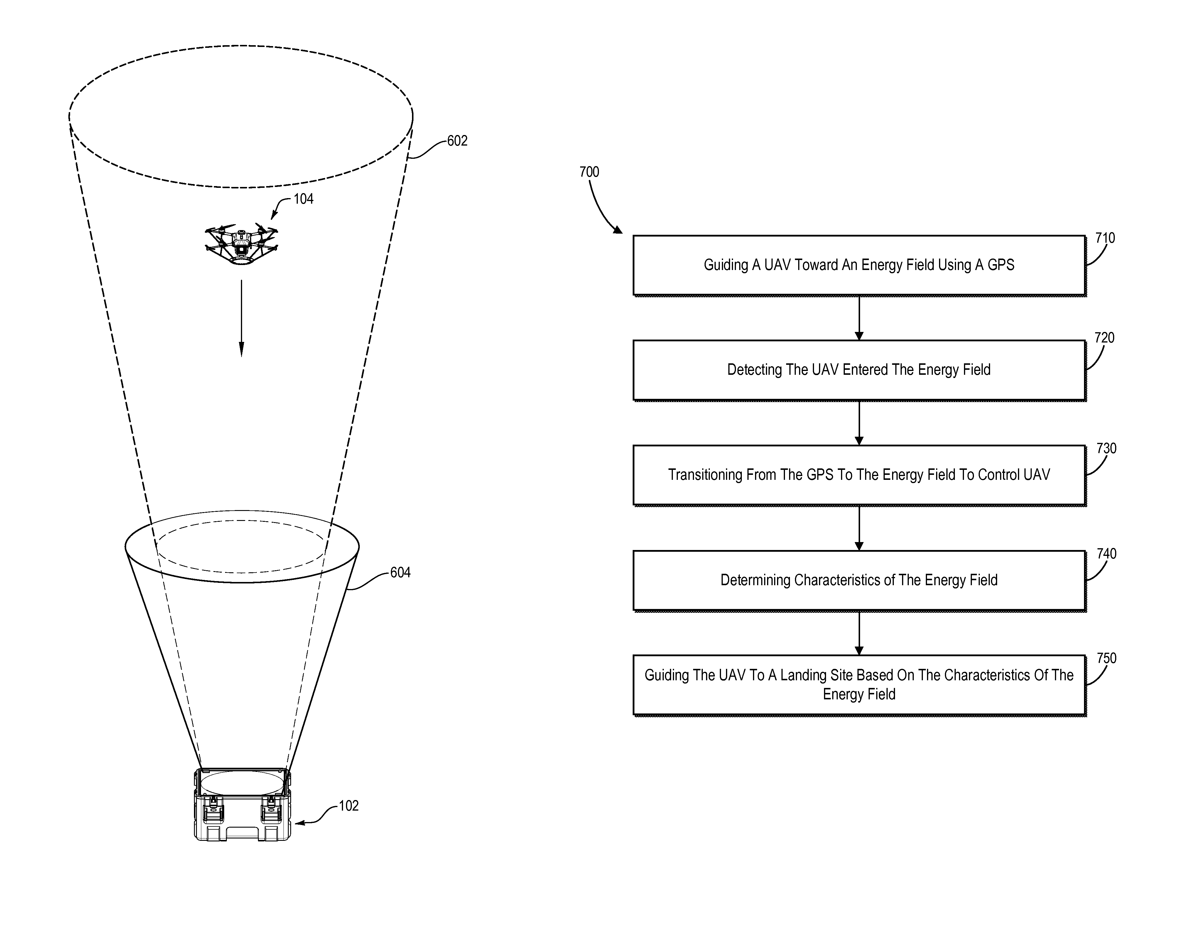
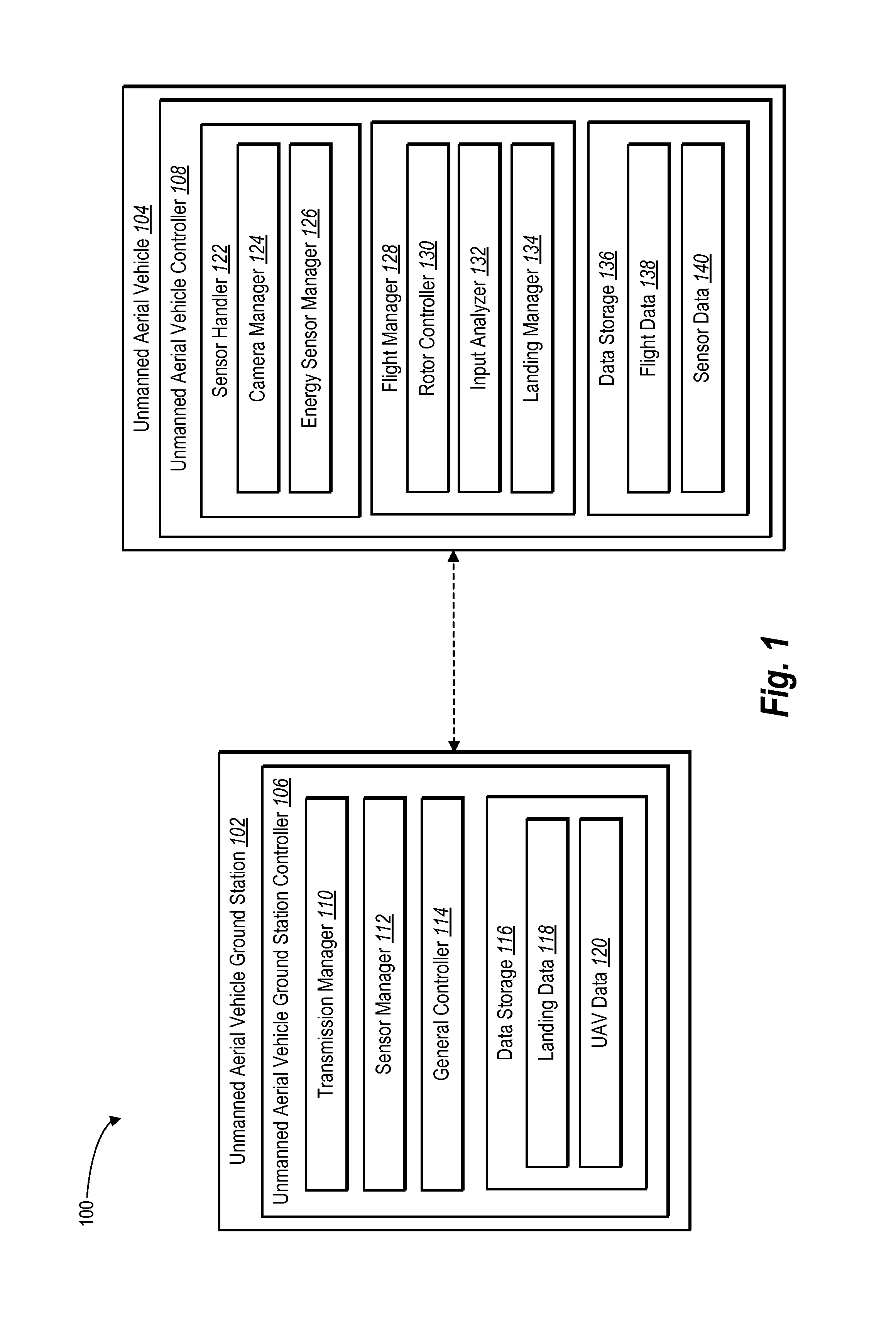
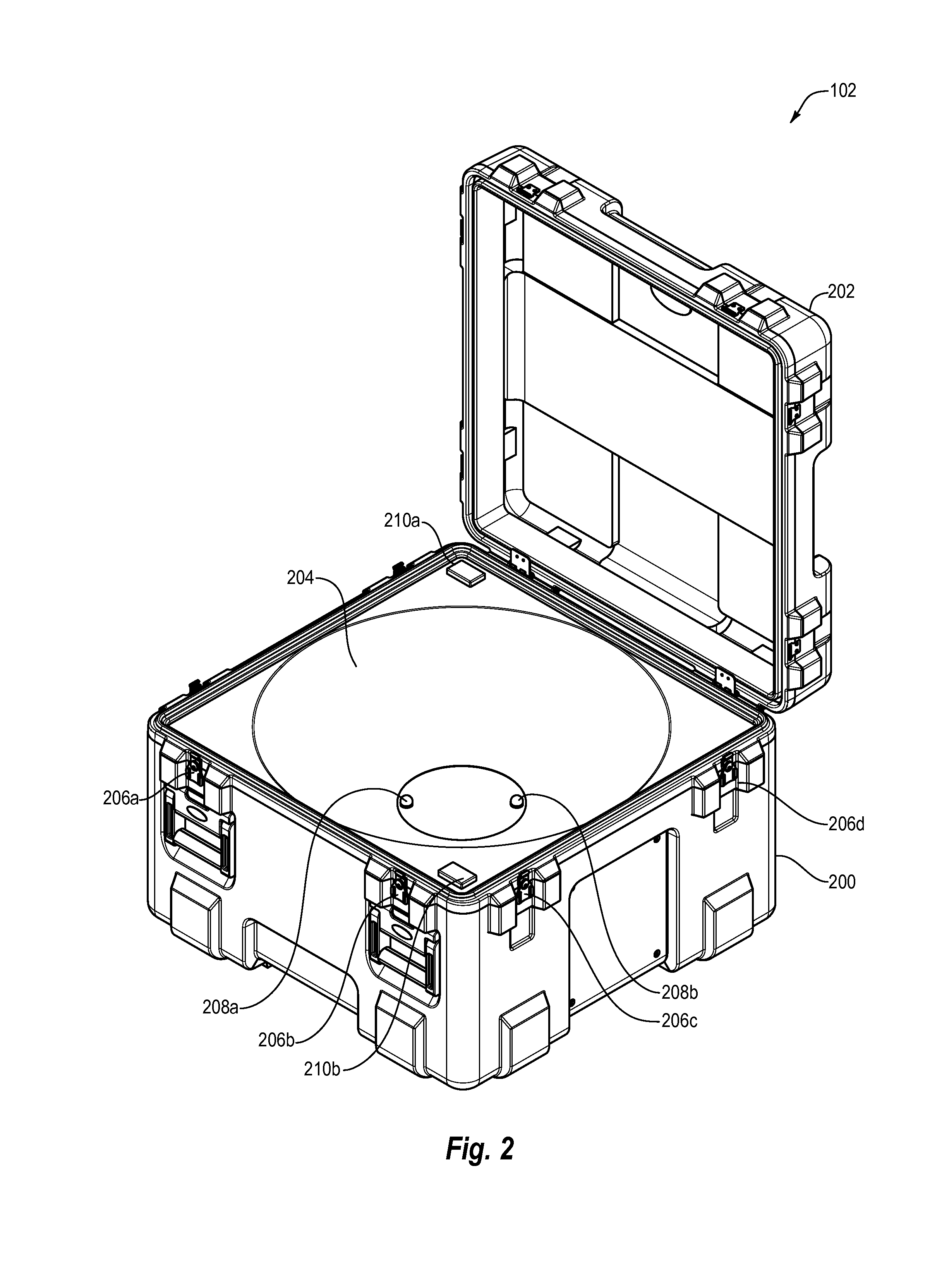
[0024]One or more embodiments described herein include an autonomous landing system. For example, the autonomous landing system described herein manages an autonomous landing of an unmanned aerial vehicle (“UAV”) in connection with a UAV ground station (“UAVGS”). The autonomous landing system described herein includes components that enable a UAV to autonomously land on a UAVGS regardless of the initial altitude of the UAV or the position of the UAVGS.

[0025]In one or more embodiments, the autonomous landing system described herein includes components that facilitate the autonomous landing of the UAV on the UAVGS by providing various guidance systems. For example, in one embodiment, the autonomous landing system can include energy transmitters on the UAVGS that produce an energy field that may be perceived by the UAV. For instance, in one or more embodiments, the energy transmitters can include light sources that produce light signals to form an energy field. The autonomous landing s...


PUM


Abstract

The present disclosure is directed toward systems and methods for enabling autonomous landing of an unmanned aerial vehicle. For example, systems and methods described herein enable autonomous landing of the unmanned aerial vehicle by providing an unmanned aerial vehicle ground station with various guidance systems for guiding the autonomous landing. In some embodiments, the guidance systems enable autonomous landing by providing one or more LEDs. In other embodiments, the guidance systems enable autonomous landing by providing various types of transmitted energy waves. In at least one embodiment, the guidance systems enable autonomous landing by providing a two-stage landing system that includes two or more types of transmitted energy.

Description

CROSS REFERENCE TO RELATED APPLICATIONS[0001]N / ABACKGROUND[0002]1. Technical Field[0003]One or more embodiments described herein relate generally to autonomous flight of an unmanned aerial vehicle. More specifically, one or more embodiments relate to autonomous landing of an unmanned aerial vehicle.[0004]2. Background and Relevant Art[0005]Aerial photography and videography are valuable tools in many applications, particularly those involving large geographic areas, such as construction, agriculture, mining, real estate, search and rescue, and surveillance. Traditionally, aerial perspectives have been obtained using photography or videography from manned aircraft or satellites. Both of these options are very costly, and neither option provides a cost-effective process to obtain real-time or near real-time imagery.[0006]Due to these limitations, there is increasing interest in the use of unmanned aerial vehicles (“UAVs”) to obtain aerial imagery. For example, a UAV including an on-bo...

Claims


Application Information

Patent Timeline
IPC IPC(8): G01S19/01G05D1/12G05D1/00G05D1/06
CPCG05D1/0676G05D1/12G05D1/0011G01S19/01G01S1/042G01S19/15G01S5/16G01S1/00G01S5/0263G01S19/48G01S2205/03
Inventor MILLER, SAMUEL GILESSANZ, CHRISTIANSIRANG, BEHROOZENOORANI, JONATHAN SHYAUN
Owner SKYCATCH
Learn More