Apparatus and method for shaped magnetic field control for catheter, guidance, control, and imaging

a magnetic field control and catheter technology, applied in the field of magnetic guiding, steering and advancing invasive medical devices, can solve the problems of affecting other equipment, dangerous to medical personnel, and only achieving skill

Inactive Publication Date: 2007-01-18
NEURO KINESIS CORP
View PDF98 Cites 175 Cited by
  • Summary
  • Abstract
  • Description
  • Claims
  • Application Information

AI Technical Summary

Benefits of technology

[0060] In one embodiment, a Hall effect ring measures the boundary plane field strength as a measure of the joystick movement. This allows the CGCI to operate on the bo

Problems solved by technology

Such skill can only be achieved after a protracted training period and extended practice.
The electromagnets in such systems produce large magnetic fields that are potentially dangerous to medical personnel and that can be disruptive to other equipment.
Therefore, there is a great and still unsatisfied need for an apparatus and method for guiding, steering, and advancing invasive devices and for accurately controll

Method used


Image

  • Apparatus and method for shaped magnetic field control for catheter, guidance, control, and imaging
  • Apparatus and method for shaped magnetic field control for catheter, guidance, control, and imaging
  • Apparatus and method for shaped magnetic field control for catheter, guidance, control, and imaging

Examples


Embodiment Construction

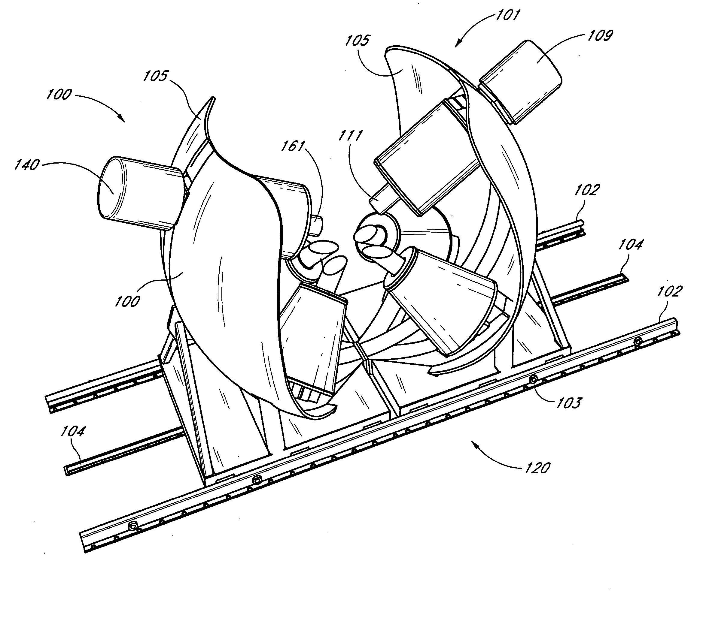
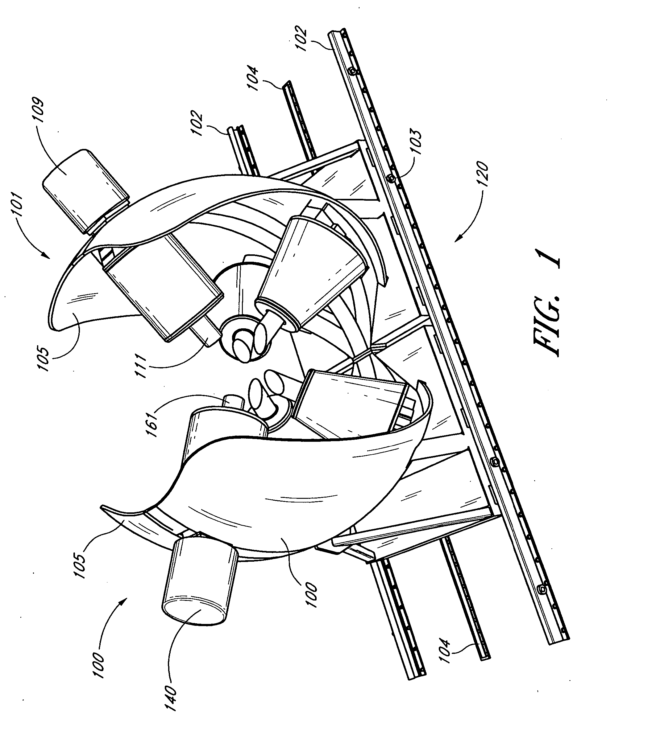
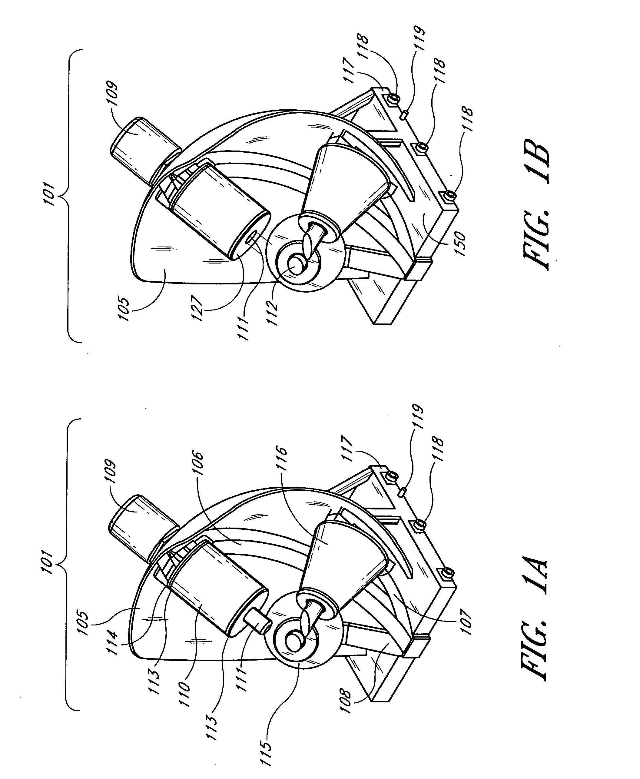
[0177]FIGS. 1, 1A and 1B are isometric drawings of a Catheter Guidance Control and Imaging (CGCI) system 1500, having a left coil cluster 100 and a right coil cluster 101 provided to rails 102. The rails 102 act as guide alignment devices. The CGCI system workstation 1500 includes a structural support assembly 120, a hydraulic system 140, a propulsion system 150, a cooling system 160, and a coil-driver system 170.

[0178] A central arc 106 supports an upper cylindrical coil 110 and two shorter arcs 107, 108 support two conical shaped coils 115, 116. The two shorter arcs 107, 108 are displaced from the central arc 106 by approximately 35 degrees. The angle of separation between the two smaller arcs is approximately 70 degrees.

[0179] At the end of each arc 106, 107 and 108 is a machined block of 1010 steel with a connection that provides for attachment of the coil assemblies 115, 116, 110.

[0180] Two curved shield plates 105 form a shield to at least partially contain and shape the ma...


PUM


Abstract

A variable magnet system for manipulating a magnetic catheter is described. In one embodiment, a cluster of electromagnets is configured to generate a desired magnetic field. In one embodiment, one or more poles of the cluster are moveable with respect to other poles in the cluster to allow shaping of the magnetic field. In one embodiment, one or more magnetic poles can be extended or retracted to shape the magnetic field. In one embodiment, the electromagnets can be positioned to generate magnetic fields that exert a desired torque and/or movement force on the catheter. In one embodiment, the catheter guidance system includes a closed-loop servo feedback system. In one embodiment, a radar system is used to determine the location of the distal end of the catheter inside the body, thus, minimizing or eliminating the use of ionizing radiation such as X-rays. The catheter guidance system can also be used in combination with an X-ray system (or other imaging systems) to provide additional imagery to the operator. The magnetic system used in the magnetic catheter guidance system can also be used to locate the catheter tip to provide location feedback to the operator and the control system. In one embodiment, a magnetic field source is used to create a magnetic field of sufficient strength and orientation to move a magnetically-responsive catheter tip in a desired direction by a desired amount.

Description

REFERENCE TO RELATED APPLICATION [0001] The entire contents of Applicant's co-pending U.S. application Ser. No. 10 / 690,472, titled “SYSTEM AND METHOD FOR RADAR-ASSISTED CATHETER GUIDANCE AND CONTROL”, filed Oct. 20, 2003, are hereby incorporated by reference.BACKGROUND [0002] 1. Field of the Invention [0003] The present invention relates to magnetic guiding, steering, and advancing invasive medical devices such as catheters and catheter-type devices. [0004] 2. Description of the Related Art [0005] Catheterization is typically performed by inserting an invasive device into an incision or a body orifice. These procedures rely on manually advancing the distal end of the invasive device by pushing, rotating, or otherwise manipulating the proximal end that remains outside of the body. Real-time X-ray imaging is a common method for determining the position of the distal end of the invasive device during the procedure. The manipulation continues until the distal end reaches the destination...

Claims


Application Information

Patent Timeline
IPC IPC(8): A61B5/05
CPCA61B19/56A61B2017/00703A61B2019/2253A61B2019/2261A61B2019/2296A61B2019/5238A61B19/22A61B2019/5263A61M25/0127A61M2025/0166A61B1/00158A61B5/0507A61B5/06A61B2019/5251A61B34/73A61B2034/732A61B2034/2063A61B34/70A61B34/25A61B2090/376A61B34/77A61B2034/2051A61B5/062
Inventor SHACHAR, YEHOSHUA
Owner NEURO KINESIS CORP
Why Eureka
Try Eureka