Systems and methods for optically projecting three-dimensional text, images and/or symbols onto three-dimensional objects

a technology of three-dimensional objects and optical projection, applied in the field of systems and methods for optical projection of three-dimensional text, images and/or symbols onto three-dimensional objects, can solve the problems of taking on ever increasing complex manufacturing tasks, and achieve the effects of improving the workforce, speeding up the production process, and enhancing the output of one individual

Active Publication Date: 2011-07-14
DELTA SIGMA
View PDF17 Cites 164 Cited by
  • Summary
  • Abstract
  • Description
  • Claims
  • Application Information

AI Technical Summary

Benefits of technology

[0030]In one embodiment, the present invention is directed to computerized optical manufacturing guidance systems and methods that enable assembly technicians and other manufacturing personnel to very efficiently, rapidly and accurately assemble any three-dimensional objects (without the use of lasers or laser technology), generally in a step-by-step order of a work process, whether having flat, curved, contoured and / or complex curved surfaces, including those objects that are relatively or very complex, such as aircrafts, submarines, missiles, military vehicles and automobiles, and objects that are not complex, such as cables, in a manner that tremendously reduces the amount of time, labor, paper products and / or computer screens that would otherwise typically be required to assemble or otherwise manufacture such objects manually, or using a laser system, and that significantly reduces or completely eliminates assembly errors, both of which result in tremendous cost savings (in time, labor, blueprints, plans, instruction manuals and / or the like). The resulting cost savings, which typically increase as the complexity of the particular object (or part) being assembled increases, can be millions of dollars for each object being assembled, such as an aircraft. Such cost savings are multiplied accordingly when more than one of the same object is being assembled. For example, if a cost savings of two million dollars is achieved in an assembly of one submarine, a cost savings of four million dollars will generally be achieved in an assembly of two such submarines, a cost savings of six million dollars will generally be achieved in an assembly of three such submarines, a cost savings of eight million dollars will generally be achieved in an assembly of four such submarines, and so forth.
[0032]Three dimensional optical projection is a brand new technology that can display three-dimensional images of objects, as well as text and symbols, onto the surfaces of three-dimensional objects, or parts thereof, without distortion. When employed in the manufacturing industry, by sequencing in order (preferably the “best” order) a series or set of complicated assembly instructions or steps (i.e., in the order of a work process), very complex assemblies or other manufactures, for example, of aircrafts, jets, helicopters, missiles, submarines, ships, boats, tanks, automobiles and a wide variety of other objects or systems, or parts thereof, can be assembled with unprecedented speed and accuracy. Such technology is expected to cause a significant improvement for manufacturing in industrialized countries. By implementing three-dimensional optical projection technology on their assembly lines, and in other production environments, businesses in countries with high-cost labor can provide a new tool to their workforces that will allow the output from one individual to be enhanced considerably. Further, third world countries are improving their workforces, so that they are taking on ever increasing complex manufacturing tasks. Three-dimensional optical projection technology is expected to enhance the productivity of workers in industrialized countries to such a large extent that third world countries' current competitive advantage (inexpensive or less expensive labor) will be greatly mitigated, with the benefit to the industrialized countries of having production performed in those countries, rather than in foreign third world countries.

Problems solved by technology

Further, third world countries are improving their workforces, so that they are taking on ever increasing complex manufacturing tasks.

Method used


Image

  • Systems and methods for optically projecting three-dimensional text, images and/or symbols onto three-dimensional objects
  • Systems and methods for optically projecting three-dimensional text, images and/or symbols onto three-dimensional objects
  • Systems and methods for optically projecting three-dimensional text, images and/or symbols onto three-dimensional objects

Examples


example

Production of Wire Harness

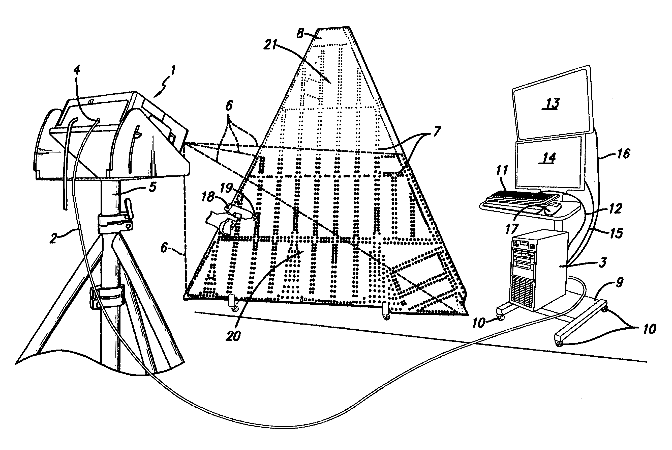
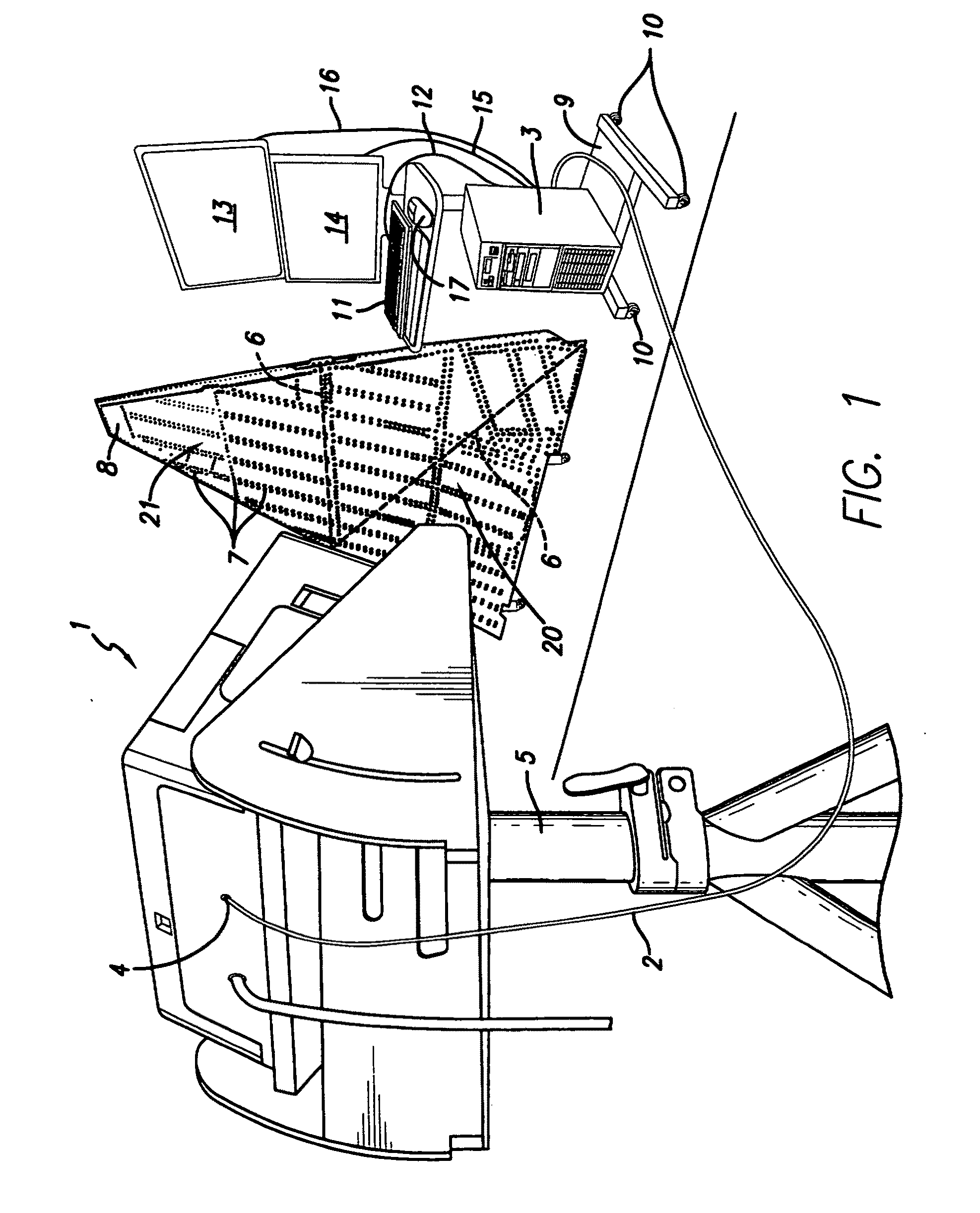
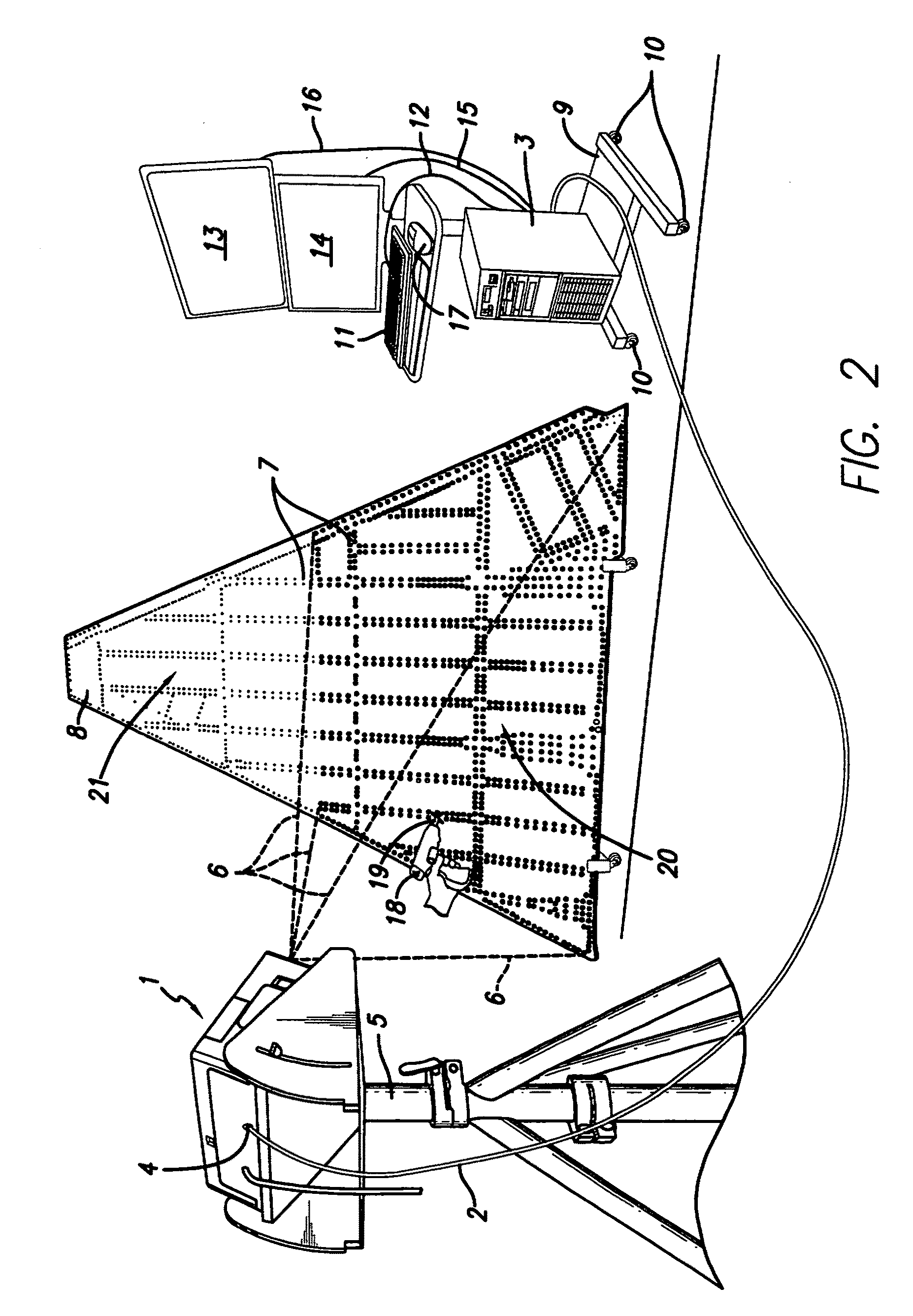
[0772]In order to test the invention in an actual assembly environment, rather than in a laboratory environment, which is not employed for assembly operations, an experiment was performed at an aircraft manufacturer facility (under the terms of a confidentiality agreement, and under the control of the inventors) to test the theory that optically projected work instructions would be helpful to assembly technicians (in terms of saving time, labor, blueprints, plans, instruction manuals, computer screens, and the like).

[0773]A particular wire harness was selected for this experiment. Abundant data from many years of cost tracking for this particular assembly was available to the inventors. A person that was skilled at making this particular wire harness averaged making it in 21 hours, whereas a person skilled at making wire harnesses in general, but not this particular wire harness, averaged making it in 28 hours.

[0774]Assembly data was input into a programmab...


PUM


Abstract

The present invention provides a method whereby the spatial relationship and orientations of one or more three-dimensional objects being illuminated by an optical projector, and the optical projector itself, can be very accurately defined both quickly and easily. The present invention also provides a novel computerized optical projection system whereby three dimensional data when viewed by the human eye projected onto three dimensional objects is not deformed as a result of the non-planar projection surface. The present invention could have many applications in many industries that include entertainment, apparel, marketing, and many others. In one embodiment, the invention provides computerized optical assembly or manufacturing guidance systems, and related methods, that provide step-by-step assembly or manufacturing instructions for instructing technicians how to assemble or manufacture three-dimensional objects or systems, or parts thereof, which may be extremely complex, such as an aircraft, or a part thereof (a vertical stabilizer, or the like), in a very efficient, rapid and accurate manner. The assembly instructions are in the form of calibrated three-dimensional text, images and / or symbols, and are projected by one or a plurality of optical projectors that are in operable communication with one or a plurality of computers onto the three-dimensional objects or systems, or component parts or skins thereof.

Description

COMPUTER PROGRAM LISTING APPENDIX[0001]All of the information, material and source code that is present in the accompanying two compact discs, which are identical, and labeled as Copy 1 of 2, and Copy 2 of 2, is hereby incorporated herein by reference in its entirety.[0002]Each compact disk contains the files that are listed below, which are two types of files (.txt and .cs. files). A few of the file names appearing below appear on two lines, rather than on one line, as is indicated if there is no file size or creation date on the second line. The files that end in .txt are identical to the corresponding files (those that have the same file name) that end in .cs, which are true C# source code files. The files that end in .cs can be used by Microsoft Visual Studio, or by a similar software development tool that supports C#, and can be compiled. The creation dates of the C# files are listed hereinbelow. The files that end in .txt are text files that can be opened by Word, Notepad, Wor...

Claims


Application Information

Patent Timeline
Patent Type & Authority Applications(United States)
IPC IPC(8): H04N13/04G06T15/00H04N13/30
CPCH04N9/3147H04N13/0425H04N9/3197H04N9/3185H04N13/30H04N13/327
Inventor HAISTY, BRETT STANTONRICHARDSON, ROGER CURTIS
Owner DELTA SIGMA
Why Eureka
Try Eureka