Probe-type connector

a connector and probe-type technology, applied in the direction of testing/measuring connectors, coupling contact members, coupling device connections, etc., can solve the problems of probe-type connectors, signal decay, transmission is not applicable to the transmission of high-frequency signals, etc., and achieve good transmission effects

Active Publication Date: 2016-08-30
BELLWETHER ELECTRONIC CORP
View PDF2 Cites 22 Cited by
  • Summary
  • Abstract
  • Description
  • Claims
  • Application Information

AI Technical Summary

Benefits of technology

[0008]It is an objective of the present invention to provide a probe-type connector which can reduce the number of conducting components through which the electric signal is transmitted such that the probe can transmit the electrical signals directly to the connecting plate like a PCB to prevent the signal attenuation and further can be applied to the transmission of high-frequency signals or high-frequency electrical energy to obtain a good transmission effect.
[0009]It is another objective of the present invention to provide a probe-type connector in which the connecting plate can be directly contacted with the probe, which therefore can omit the traditional connecting terminals and can solve the problem of the traditional connecting terminals having to be installed one by one. Thus, an effect of easy assembly is obtained.
[0011]Compared with the prior art, the present invention has the following effects. By means of the flexible connecting arm extending from the probe terminal, the electrical signals can be transmitted directly to the connecting plate, which prevents the excessive connecting components on the transmission path and the signal attenuation caused by undue transmission path. Thus, the present invention can be applied to the transmission of high-frequency signals or high-frequency electrical energy and can obtain a good transmission effect.

Problems solved by technology

However, the existing probe-type connector has the follow disadvantages.
Also, the transmission between the retractable terminal and the connecting terminal is the contact transmission, which is likely to cause the problem of signal decay during the transmission.
Thus, such transmission is not applicable to the transmission of high-frequency signals and is even difficult to be used in the transmission of high-frequency signals.

Method used


Image

  • Probe-type connector
  • Probe-type connector
  • Probe-type connector

Examples


Embodiment Construction

[0019]The detailed description and technical details of the present invention will be explained below with reference to accompanying figures. However, the accompanying figures are only for reference and explanation, but not to limit the scope of the present invention.

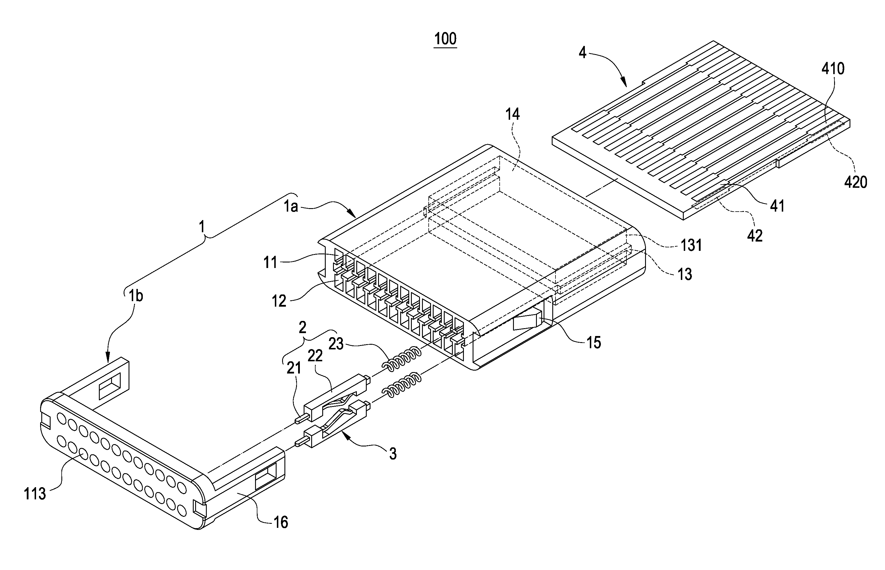
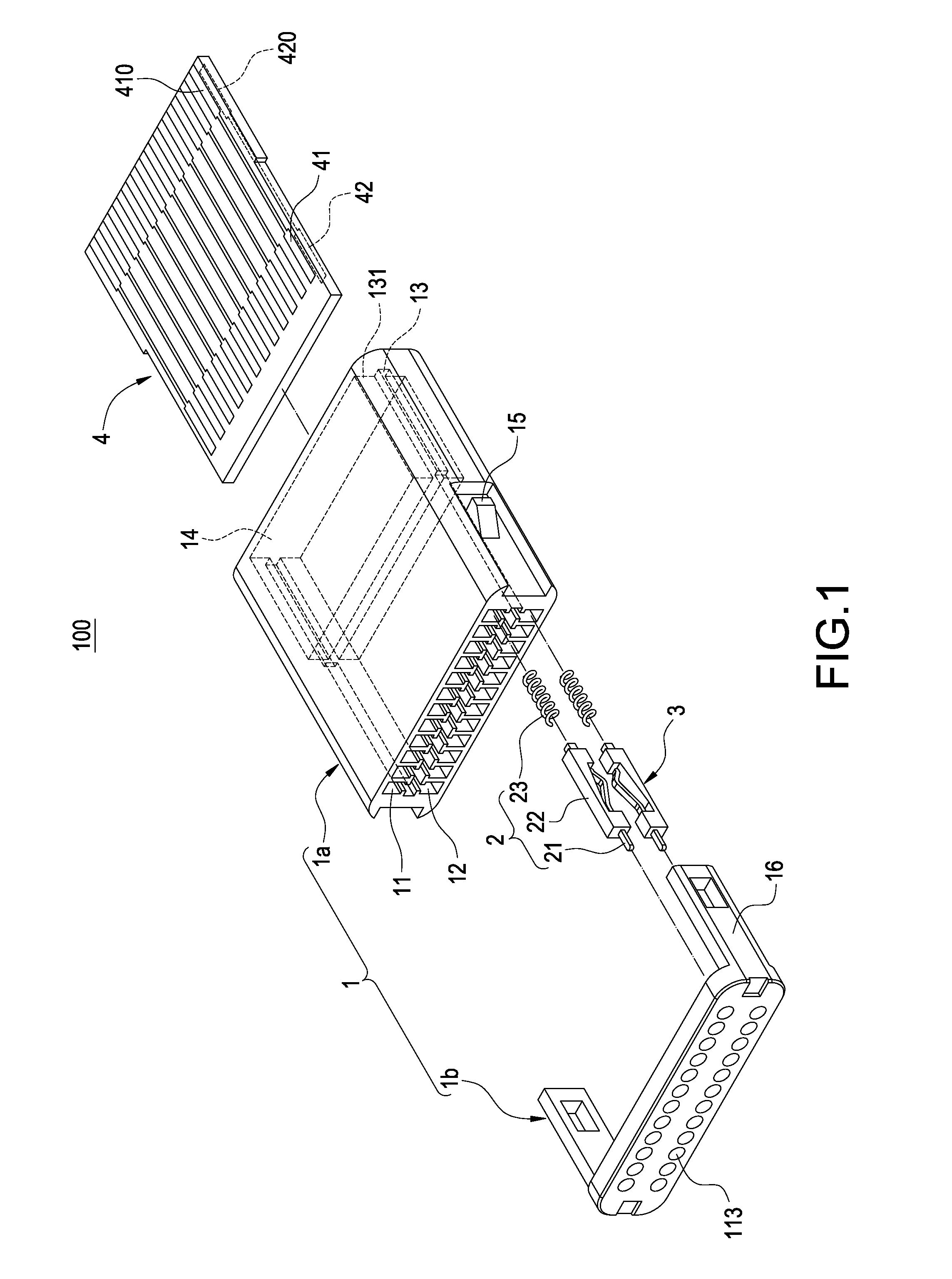
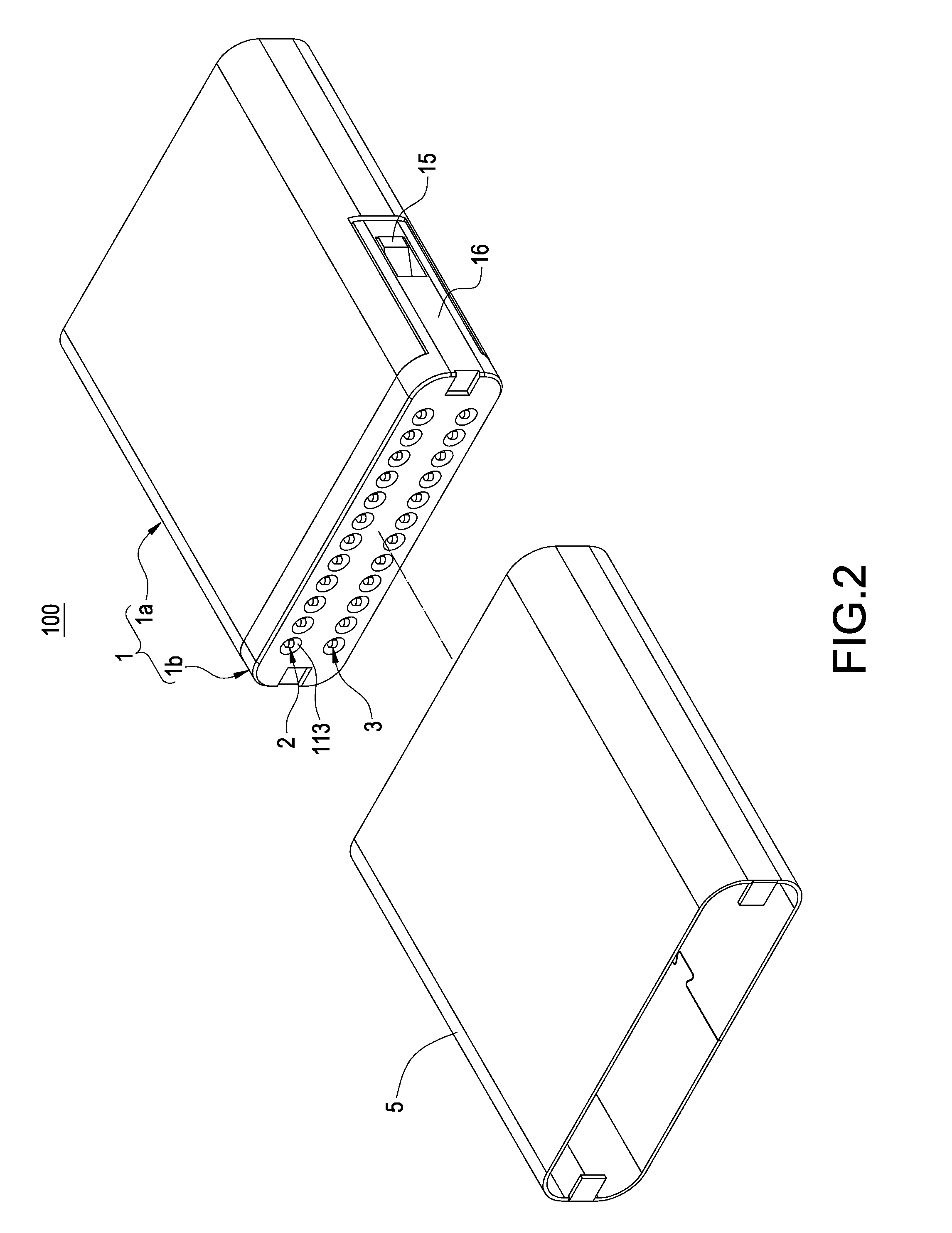
[0020]The present invention provides a probe-type connector, as shown in the accompanying figures, which is disposed in an installation space (not shown) of an electronic device (not shown) such as the installation spaces of batteries, a power supply unit, and electric components. When a connected product 800 like a battery, a power supply unit, or an electronic component (shown in

[0021]FIG. 6) is installed in the installation space and is then connected against the connector 100 of the present invention, the electrical energy or signals of the connected product 800 can be transmitted to the electronic device.

[0022]As shown in FIGS. 1-5, the connector 100 of the present invention comprises an insulating body 1, at least...


PUM


Abstract

A probe-type connector includes an insulating body having a receiving space and a plugging slot which both communicate with each other, a probe set received in the receiving space and including a probe terminal, an insulating part, and an elastic part, and a connecting plate plugged into the insulating body corresponding to the plugging slot and having a connecting portion. The probe terminal has a connecting segment, and a flexible connecting arm extending from the connecting segment toward the plugging slot. The insulating part is connected between the connecting segment and the elastic part that enables the insulating part and the probe terminal to reciprocate in the receiving space. The flexible connecting arm is electrically connected to the connecting portion. Therefore, the probe terminal can transmit electrical signals directly to the connecting plate, which can be applied to the transmission of high-frequency signals or electrical energy.

Description

BACKGROUND OF THE INVENTION[0001]1. Field of the Invention[0002]The present invention relates to an electrical connector, in particular, to a probe-type connector which is applicable to transmit high-frequency signals.[0003]2. Description of Related Art[0004]The probe-type connector is usually disposed in an installation space of an electronic device such as the installation spaces of batteries, a power supply unit, and electronic components. The probe-type connector is mainly electrically connected to the batteries or the power supply unit to provide electrical energy for the electronic device or is electrically connected to the electronic components to transmit signals to the electronic device.[0005]The existing probe-type connector mainly comprises an insulating part, plural probes, and plural connecting terminals. The probe is movably disposed in the insulating part and comprises a retractable terminal and an elastic component. The elastic component is supported between the retr...

Claims


Application Information

Patent Timeline
Patent Type & Authority Patents(United States)
IPC IPC(8): H01R13/24H01R13/66H01R12/72H01R12/58H01R12/70H01R13/514
CPCH01R13/665H01R12/721H01R13/2421H01R12/87H01R12/58H01R12/7005H01R13/514H01R2201/20
Inventor CHEN, KUAN-WUKUO, CHIA-HUNGLEE, HSING-YU
Owner BELLWETHER ELECTRONIC CORP
Why Eureka
Try Eureka