Mass-distributing device and moulding device comprising a mass distributing device of this type

a technology of mass distribution and moulding device, which is applied in the direction of meat pressing, butchering, food shaping, etc., can solve the problems of undesirable effect on the behaviour of moulded products and deviations in the final produ

Active Publication Date: 2016-09-06
MAREL TOWNSEND FURTHER PROCESSING
View PDF19 Cites 7 Cited by
  • Summary
  • Abstract
  • Description
  • Claims
  • Application Information

AI Technical Summary

Benefits of technology

[0011]In a similar manner, the post-filling zone is a section of the flexible abutment element which, viewed in the described direction of movement, is situated downstream from the filling area. During use, the post-filling zone pressure means press this zone of the flexible abutment element against the moulding member at a contact pressure which is higher than the filling pressure, so that leakage of mass in the direction of movement is also prevented during filling, in other words to the downstream start of the mould cavity. Expediently, the length of the post-filling zone is at least equal to the largest dimension of a mould cavity, said length and largest dimension again being viewed in the direction of movement. In addition, this contact pressure, which is greater than the filling pressure, exerts a force on the mass filled into the mould cavity for some time after filling, which is advantageous for some types of mass, such as meat masses.
[0017]In one embodiment, each pressure element comprises an elongate profiled section which extends in the transverse direction of the flexible abutment element, and in which, in the mass-distributing device, several elongate profiled sections are arranged at a distance from one another on a side of the flexible abutment element which is designed to be turned away from the moulding member, and in which the member of each pressure element which can expand under fluid pressure engages with or, if desired, is connected to the elongate profiled section of said pressure element in order to exert a pressure force on the flexible abutment element via the elongate profiled section. The elongate profiled sections can direct the contact pressures locally into the flexible abutment element, so that the contact pressures can be accurately set for each zone.
[0019]It is possible for the pressure means to be provided with one or more pressure sensors in order to detect the current contact pressure in each zone of the flexible abutment element. Each zone then preferably has at least one pressure sensor by means of which the contact pressure in said zone can be detected. The pressure sensors are, for example, connected to a control unit which receives the contact pressures detected by the pressure sensors. The control unit is designed to control the pressure elements in order to set the contact pressures in the different zones. By means of the pressure sensors and the control unit, it is possible to control the contact pressures accurately.
[0023]Advantageously, in addition to said pressure elements expandable under fluid pressure, the pressure means comprise one or more chambers which preferably extend parallel to the pressure elements, which chambers are arranged between the pressure elements and the flexible abutment element in order to be able to readily compensate for unevenness of the moulding member, for example a non-constant radius of a moulding drum. On the outer circumference, the housing may be provided with reinforcement ribs or strips which extend in the axial and / or circumferential direction in order to impart the desired strength and rigidity to the structure.

Problems solved by technology

Since it has now been found that during use of this known moulding device with mass-distributing device there is a risk of the final product showing a number of undesirable deviations, in particular a lip or appendage on in particular the outer circumference of the moulded product, and inclusions of air which may have an undesirable effect on the behaviour of the moulded product during subsequent processing steps, such as shrinking during frying, baking, etc.

Method used


Image

  • Mass-distributing device and moulding device comprising a mass distributing device of this type
  • Mass-distributing device and moulding device comprising a mass distributing device of this type
  • Mass-distributing device and moulding device comprising a mass distributing device of this type

Examples


Embodiment Construction

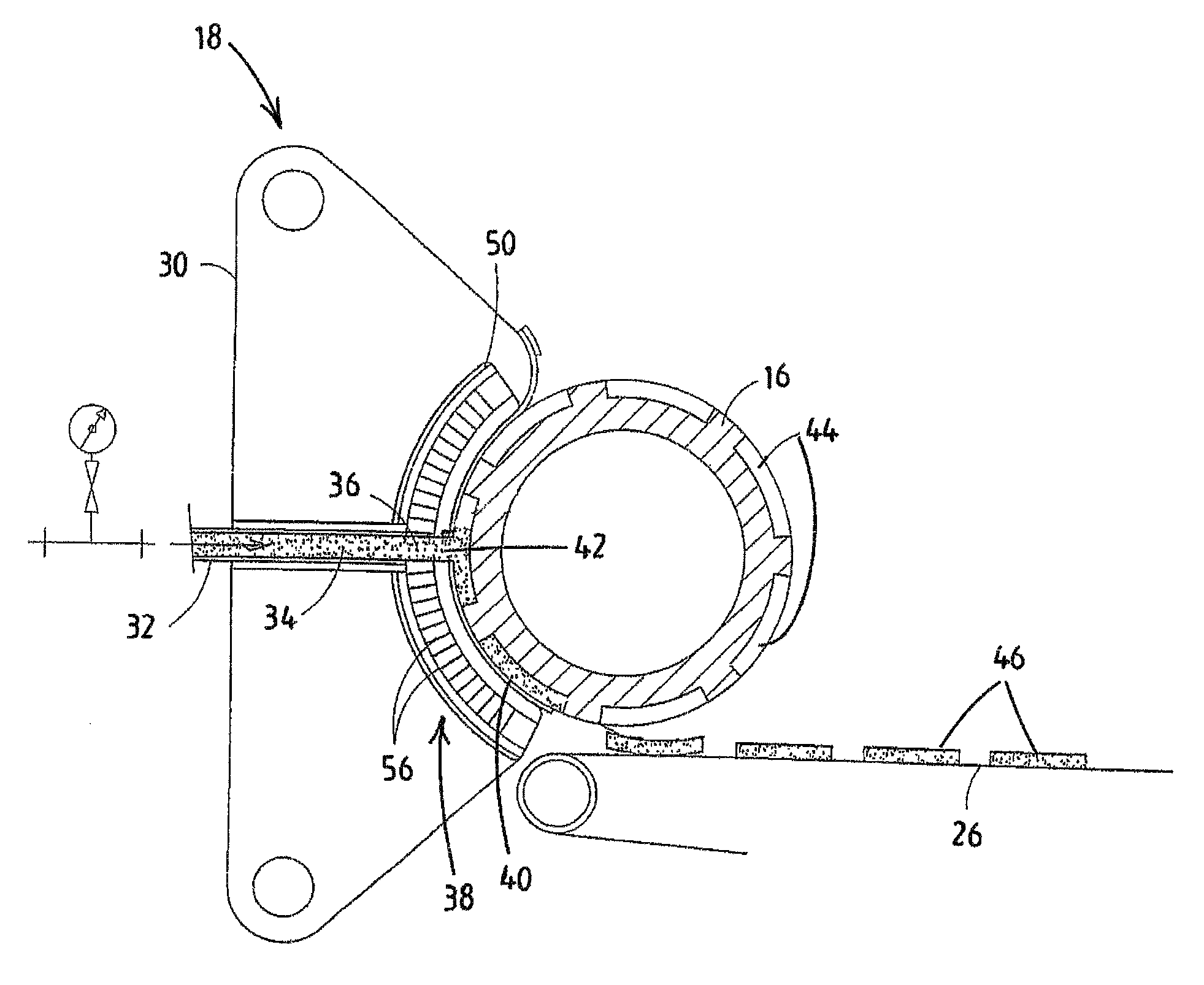
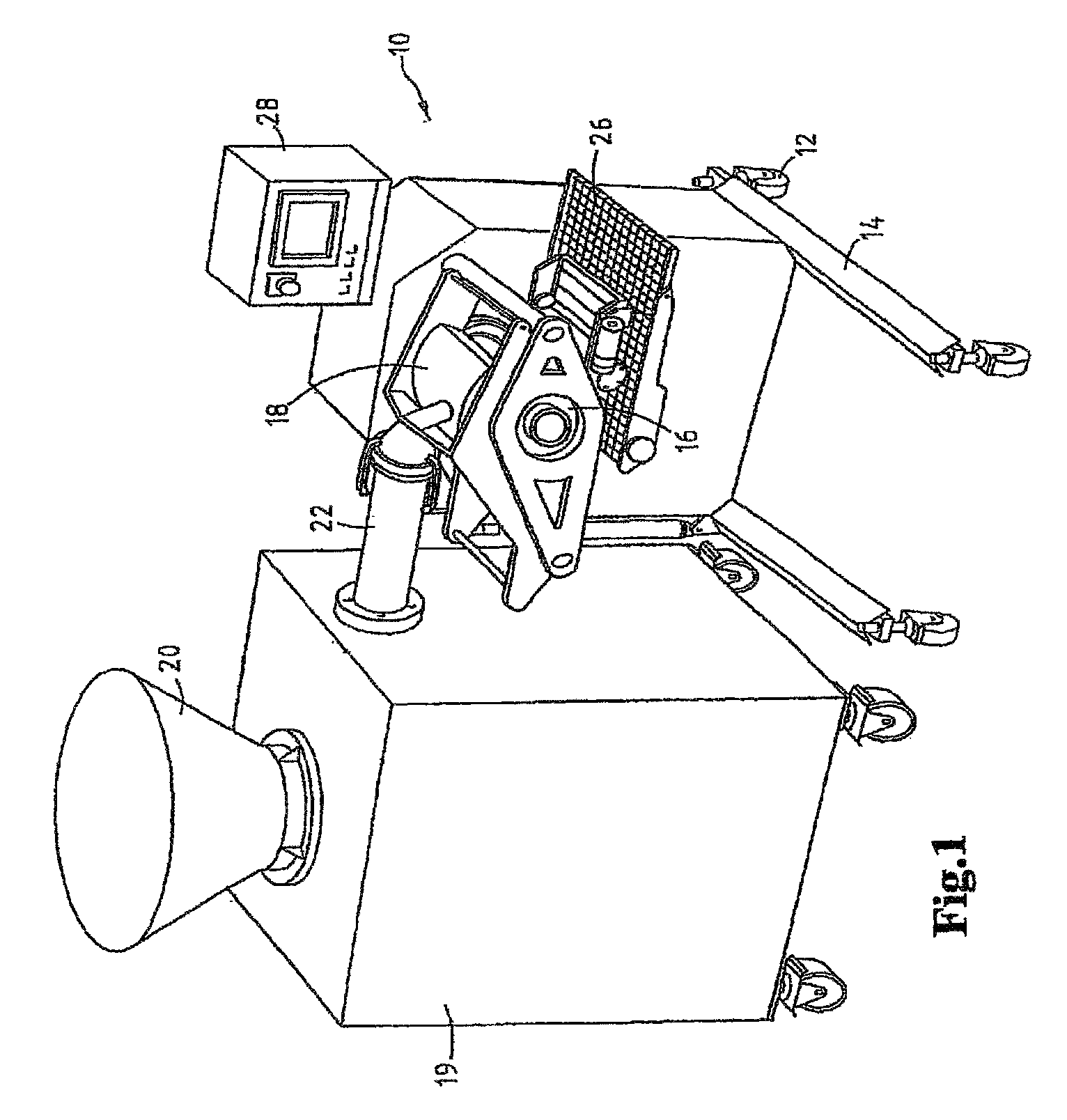
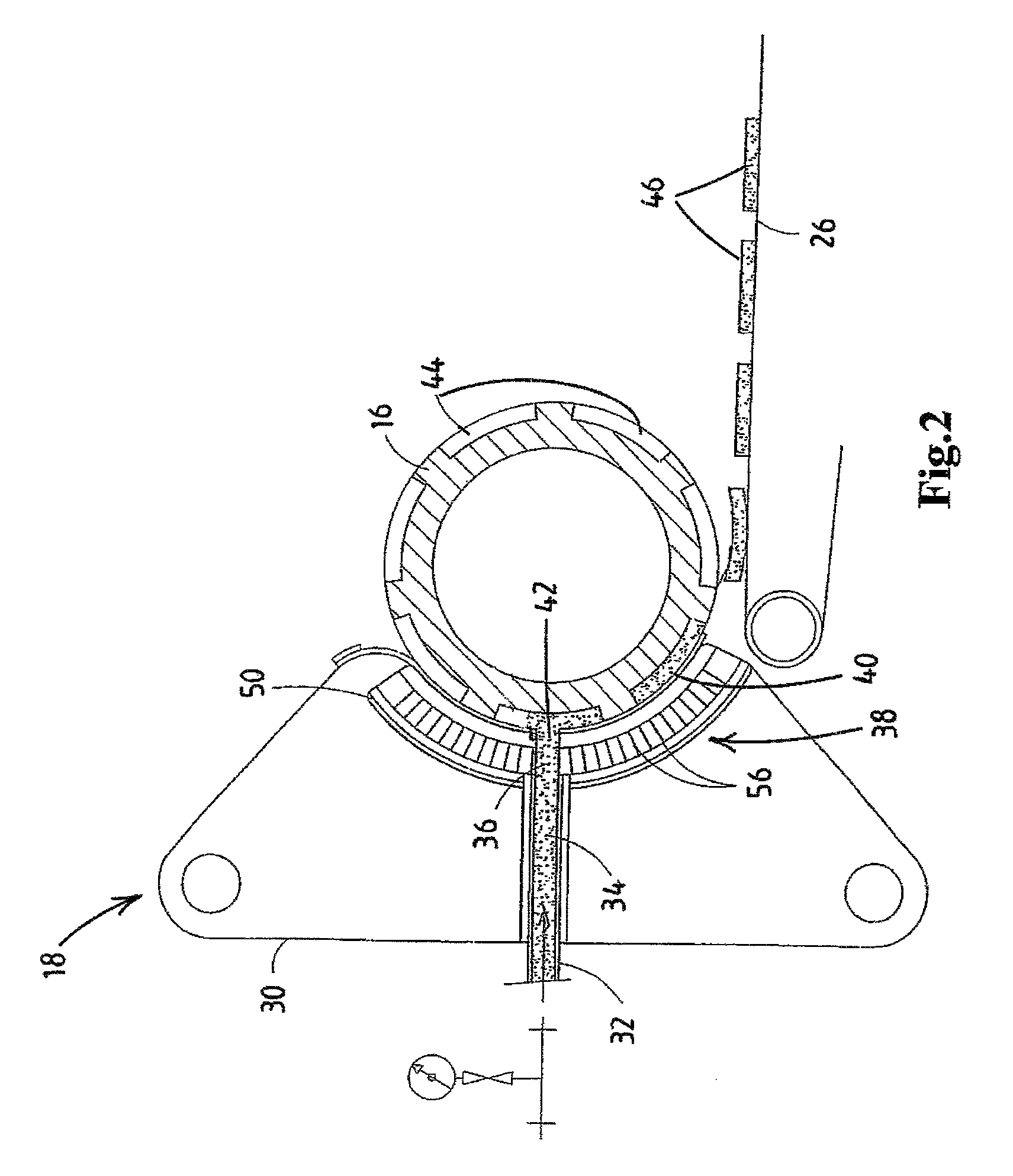
[0041]FIG. 1 shows a view in perspective of an embodiment of a moulding device according to the invention. The moulding device is denoted overall by reference numeral 10. The moulding device 10 comprises a frame 14 which can be displaced by means of castors 12. A moulding member 16, in this case a moulding drum which is arranged rotatably about a horizontal axis and which is, for example, driven by a drive means (not shown in more detail) such as an electric motor, is arranged on the frame 14. The moulding member 16 is provided with mould cavities which are not visible in FIG. 1, in this case on the outer circumference of the moulding drum. A mass-distributing device 18 according to the invention for distributing a mass to be moulded over the mould cavities of the moulding member 16 is in close contact therewith in a manner which is described in more detail below. A displaceable supply device 19 with introduction funnel 20 and a ((semi)continuously operating) pump (not illustrated) ...


PUM


Abstract

A mass-distributing device for supplying a mass of foodstuff starting materials suitable for consumption, in particular a meat mass, to one or more mold cavities of a molding member for molding three-dimensional products from the mass is provided. The device comprises a housing, which has an open side which can be turned towards the molding member, in which a flexible abutment element for the housing to abut the molding member is arranged. In the housing, a through-passage for the mass extends from an introduction opening in the housing to a discharge, which discharge opens at the open side of the housing. Pressure means are provided in order to position the flexible abutment element under pressure against the plane of the molding member comprising one or more mold cavities, the pressure means being designed to set contact pressures in separate zones of the flexible abutment element.

Description

CROSS-REFERENCE TO RELATED APPLICATIONS[0001]This application is a Divisional of application Ser. No. 13 / 259,923, filed on Sep. 23, 2011, now issues as U.S. Pat. No. 9,044,029, which is the National Phase of PCT International Application No. PCT / NL2010 / 000058, filed on Mar. 26, 2010, which claims priority under 35 U.S.C. 119(a) to Patent Application No. 2002672, filed in The Netherlands on Mar. 26, 2009, all of which are hereby expressly incorporated by reference into the present application.BACKGROUND OF THE INVENTION[0002]1. Field of the Invention[0003]According to a first aspect, the invention relates to a mass-distributing device for distributing a mass of foodstuff starting materials suitable for consumption, in particular a meat mass, over one or more mould cavities of a moulding member for moulding three-dimensional products from said mass.[0004]2. Description of Background Art[0005]A mass-distributing device of this type is known, for example, from WO 2004002229. In order to...

Claims


Application Information

Patent Timeline
Patent Type & Authority Patents(United States)
IPC IPC(8): A23P30/10A22C7/00
CPCA23P30/10A22C7/0069A22C7/0092A22C7/003A22C7/0076A23V2002/00
Inventor VAN DER EERDEN, HENDRICUS FRANCISCUS JACOBUS MARIAMESKENDAHL, DIRKDEKKER, THOMAS WILLEM
Owner MAREL TOWNSEND FURTHER PROCESSING
Why Eureka
Try Eureka