Turbo chiller

a chiller and chiller technology, applied in refrigeration machines, lighting and heating apparatus, refrigeration safety arrangements, etc., can solve the problems of large amount of refrigerant leakage into the atmosphere, detection of refrigerant leakage, etc., to reduce the amount of refrigerant, prevent a large amount of refrigerant emission, and reduce the number of set refrigerant detection sensors

Active Publication Date: 2013-05-30
MITSUBISHI HEAVY IND LTD
View PDF2 Cites 16 Cited by
  • Summary
  • Abstract
  • Description
  • Claims
  • Application Information

AI Technical Summary

Benefits of technology

[0024]According to the present invention, even if a slight amount (like so-called crab bubbles) of refrigerant leakage occurs from the pipe joint groups of the refrigerant cooling pipe system and the lubricant pipe system and from the joint group of the various replacement components, the refrigerant leakage can be detected by the refrigerant detection sensor at the time at which the leaking refrigerant has flown downward to be distributed and pool at a concentration detectable by the refrigerant detection sensor at the pre-identified point at which the refrigerant detection sensor is arranged. Accordingly, the slight amount of refrigerant leakage can be detected by at least one refrigerant detection sensor at its initial stage. As a result, early discovery and early treatment of the refrigerant leakage can prevent a large amount of refrigerant emission, and can reduce the amount of refrigerant at the time of refilling. Further, the number of the set refrigerant detection sensors can be minimized, and hence simplified configuration and reduced costs can be achieved.

Problems solved by technology

Unfortunately, the refrigerant leakage can be detected only at the time at which the refrigerant has leaked up to a concentration at which the refrigerant can be detected by a refrigerant detection sensor set in the machine room or at the time at which the chiller trips after discharge of the entire refrigerant.
In both cases, a large amount of refrigerant leaks to be emitted into the atmosphere.

Method used


Image

  • Turbo chiller
  • Turbo chiller
  • Turbo chiller

Examples


first embodiment

[0036]Hereinafter, a first embodiment of the present invention is described with reference to FIG. 1 and FIG. 2.

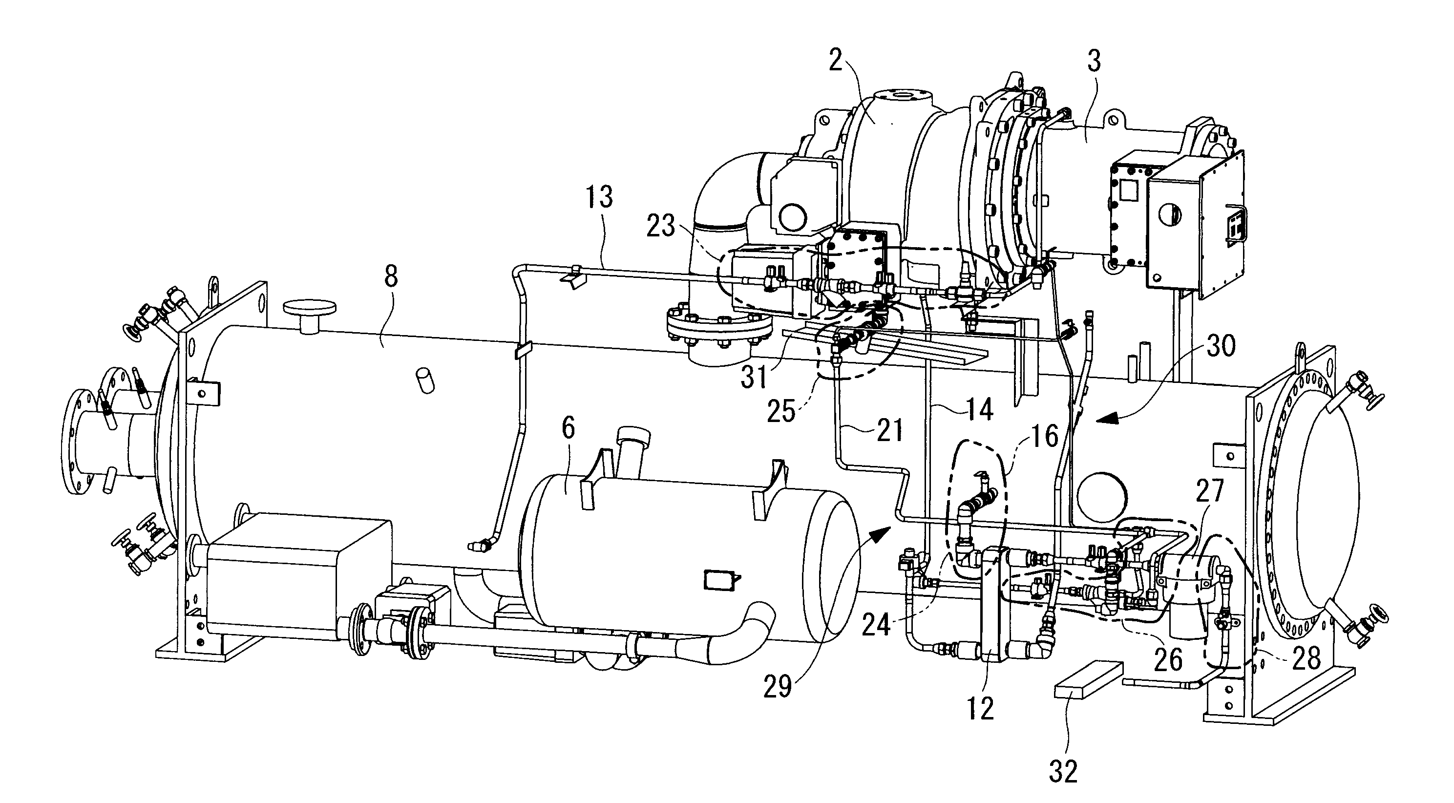
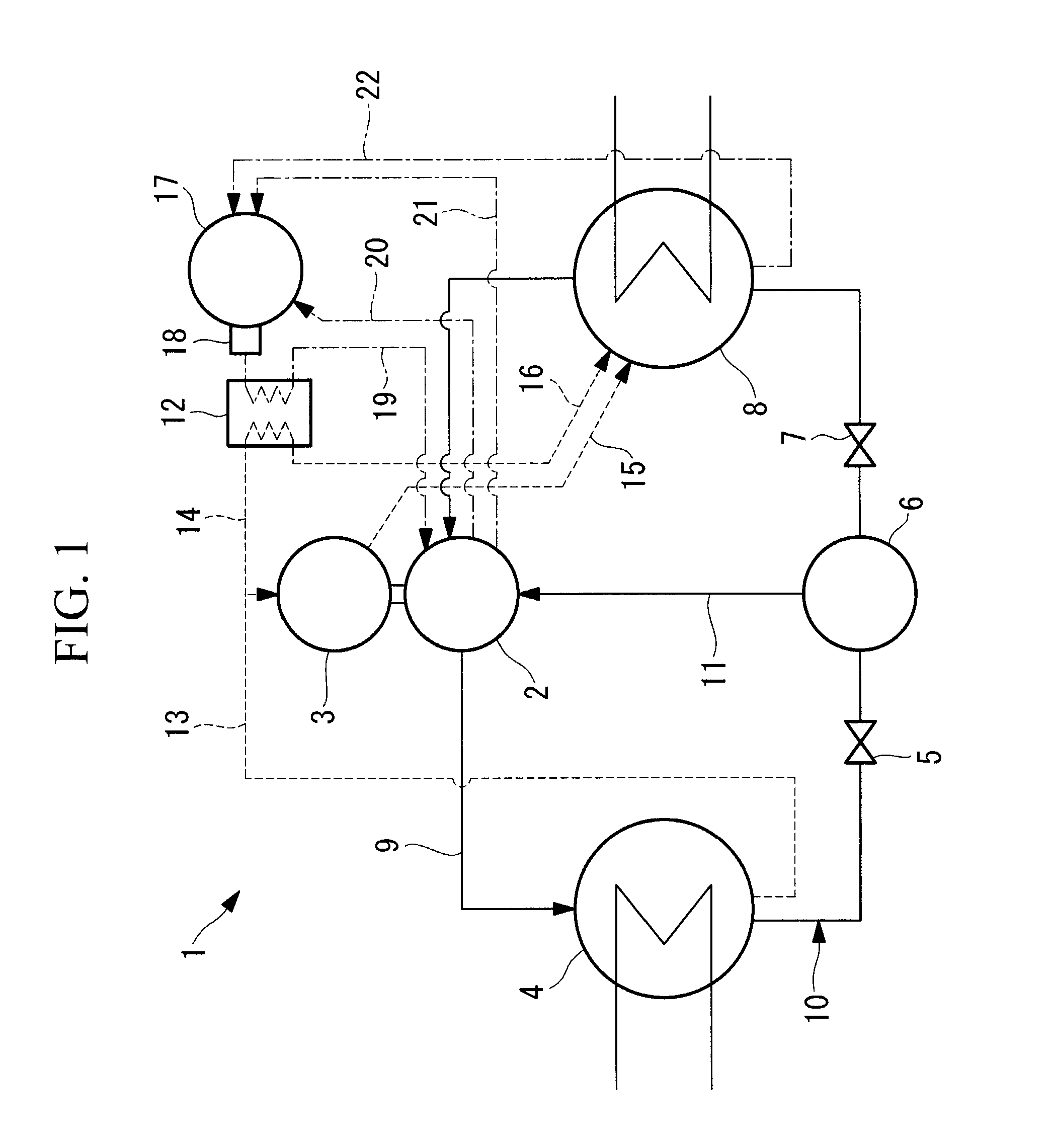
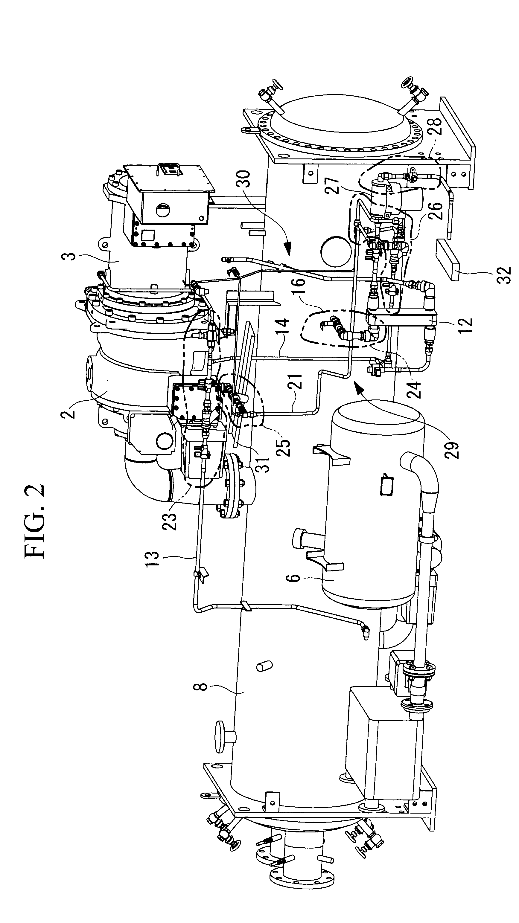
[0037]FIG. 1 illustrates a refrigeration cycle of a turbo chiller 1 according to the present embodiment, and FIG. 2 illustrates an external perspective view of the turbo chiller 1, from which part of devices thereof are omitted.

[0038]The turbo chiller 1 includes a turbo compressor 2, an electric motor (may be simply referred to as “motor” in some cases) 3 that drives the turbo compressor 2, a condenser 4, a higher-stage expansion valve 5, an economizer 6, a lower-stage expansion valve 7, an evaporator 8, and the like. These devices are connected to each other by a refrigerant pipe 9, and thus constitute a closed refrigeration cycle 10.

[0039]The turbo compressor 2 and the electric motor 3 are configured as an electric compressor having a sealed structure in which housings of the turbo compressor 2 and the electric motor 3 are integrally coupled to each other. In the present...

second embodiment

[0060]Next, a second embodiment of the present invention is described with reference to FIG. 3 to FIG. 5.

[0061]The present embodiment relates to a turbo heat pump example. The present embodiment is different from the first embodiment described above in that: the condenser 4 and the evaporator 8 are each configured as a rectangular plate heat exchanger; the economizer 6, the oil tank 17, an oil separator 33, and the like are placed around the condenser 4 and the evaporator 8; and the turbo compressor 2 and the motor 3 having the integrated and sealed structure, the oil cooler 12, and the like are placed above the condenser 4 and the evaporator 8. The present embodiment is the same as the first embodiment in the configuration of the refrigeration cycle 10 and the basic configuration including the refrigerant cooling pipe systems 13 to 16 and the lubricant pipe systems 19 to 22, and hence different points are mainly described below.

[0062]Similarly to the first embodiment, the refrigera...


PUM


Abstract

In a turbo chiller, pipe joint groups (23 to 26) provided to refrigerant cooling pipe systems (13 to 16) and lubricant pipe systems connected to a turbo compressor (2) and a motor (3), as well as a joint group (28) of various replacement components (27) provided to the pipe systems, are intensively placed, and at least one refrigerant detection sensor (32) is arranged below the intensive placement region (30) of the joint groups (23 to 28) and at a pre-identified point at which a slight amount of refrigerant that leaks from each of the joint groups (23 to 28) and flows downward is distributed and pools at a high concentration, whereby the slight amount of refrigerant leakage can be detected by the refrigerant detection sensor (32).

Description

TECHNICAL FIELD [0001]The present invention relates to a turbo chiller including a turbo heat pump.BACKGROUND ART [0002]A turbo chiller including a turbo heat pump can store a larger amount of refrigerant than other chillers and heat pumps, and a turbo chiller having, for example, a capacity at the level of 500 refrigeration ton can store about 700 to 800 kg of refrigerant. Refrigerants used for turbo chillers at present are HFC134a, HFC245fa, and the like that are considered not to harm the ozone layer, but these refrigerants all have a high global warming potential (GWP) and are considered to have a significant influence on global warming.[0003]Further, such a turbo chiller is installed in a machine room of a building in many cases. If refrigerant leakage should occur due to an accident or the like, the refrigerant, which is heavier than air, pools in a lower portion. Unfortunately, the refrigerant leakage can be detected only at the time at which the refrigerant has leaked up to ...

Claims


Application Information

Patent Timeline
Patent Type & Authority Applications(United States)
IPC IPC(8): F25B31/00
CPCF25B31/004F25B49/005F25B2500/222
Inventor UEDA, KENJIHASEGAWA, YASUSHIMATSUKURA, NORIYUKI
Owner MITSUBISHI HEAVY IND LTD
Why Eureka
Try Eureka