
Propulsion assembly for a dart-based electrical discharge weapon

Active Publication Date: 2016-09-06
PARK YONG S
View PDF27 Cites 15 Cited by
  • Summary
  • Abstract
  • Description
  • Claims
  • Application Information

AI Technical Summary

Benefits of technology

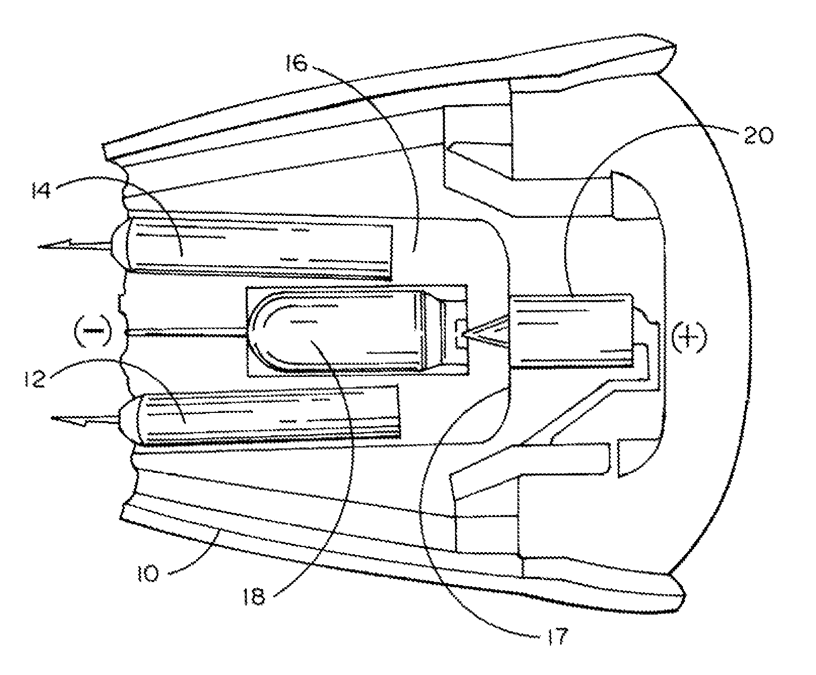
The present invention is an improved system for launching two electrode wire-tethered darts towards a target to disable it using electrical pulses. It uses a cartridge with a U-shaped channel that propels the darts. The system is efficiently propelled by a sudden release of compressed gas from a sealed storage tank caused by the penetration of the tank by a conical penetrator, which is forced by an electrically-induced ignition of a pyrotechnic material. The conical shape of the penetrator and the axial penetration of the tank result in a perfectly symmetrical rush of gas into a relatively confined volume, including the dart channel, which propels the darts towards the target in an efficient manner.

Problems solved by technology

Unfortunately Simpson's disclosure shows a configuration in which the released gas has to fill an entire cartridge interior in order to propel both darts.
Such a design suffers from a reduced propulsion efficiency because of the large volume that needs filling in order to build up the internal pressure sufficient to force the darts out of the cartridge with some sufficient level of initial acceleration to reach a remote target.
A second potential difficulty is the lack of symmetry in the relation of the darts and the tank of compressed gas which can cause initial instantaneous differences in pressure levels at the two darts which can interfere with dart accuracy and timing.

Method used


Image

  • Propulsion assembly for a dart-based electrical discharge weapon
  • Propulsion assembly for a dart-based electrical discharge weapon
  • Propulsion assembly for a dart-based electrical discharge weapon

Examples


Embodiment Construction

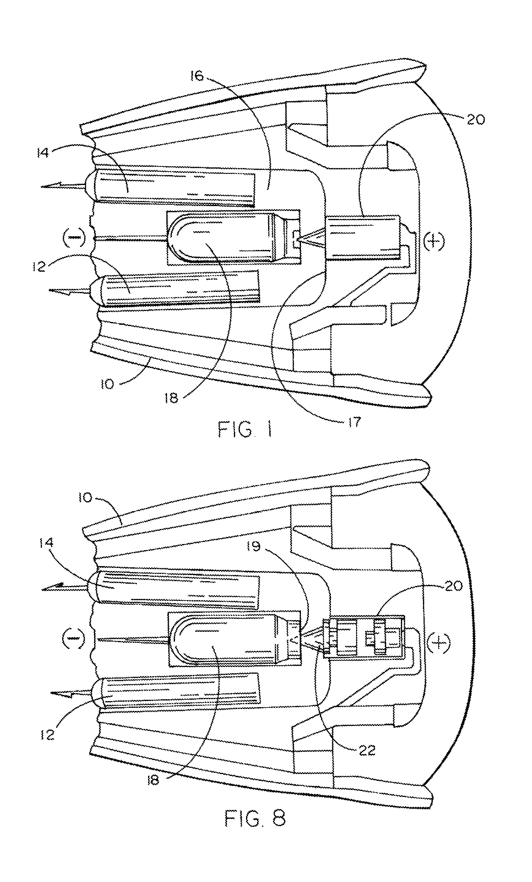
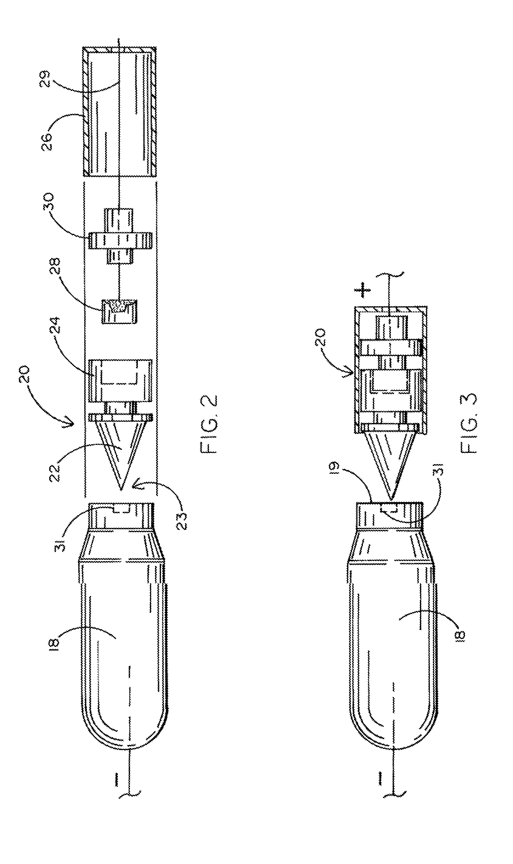
[0013]Referring to the accompanying drawings and particularly FIGS. 1-3, it will be see that a preferred embodiment of the present invention comprises a cartridge 10 having a pair of electrode darts 12 and 14 which are normally wire-tethered (but the wires are not shown in order to avoid obfuscation of the invention). The darts 12 and 14 reside in a u-shaped channel 16 which symmetrically encloses a sealed tank 18 holding a quantity of compressed gas which may be for example CO2. One axial surface 19 of tank 18 is in juxtaposition with a penetration assembly 20, the latter shown in detail in FIGS. 2 and 3.

[0014]Assembly 20 comprises a conical penetrator 22 which has a sharp conical point 23 at one end and a cylindrical portion 24 at the other as shown best in FIGS. 4-7. Cylindrical portion 24 provides a chamber 25 which receives a cylindrically shaped quantity of pressed pyrotechnic material 28. Material 28 is in intimate contact with an ignition wire 29 which extends through a conn...


PUM


Abstract

An assembly for use in propelling electrode darts toward a distant target is deployed in an electrical discharge weapon. The assembly comprises a cartridge having a u-shaped channel terminating in apertures through which wire-tethered darts are propelled. Propulsion is achieved relatively efficiently using the sudden release of compressed gas from a sealed storage tank in response to penetration by a conical penetrator forced by an electrically-induced ignition of a pyrotechnic material to accelerate toward and penetrate the tank at an axial surface. The conical shape of the penetrator and the axial penetration of the tank produces a precisely symmetric rush of gas into a relatively confined volume including the dart channel to propel the darts toward the target in an efficient manner. Paper stickers may cover the dart exit apertures to permit initial pressure buildup before the darts penetrate the stickers as they are propelled toward the target.

Description

BACKGROUND OF THE INVENTION[0001]1. Field of the Invention[0002]The present invention relates generally to the field of non-lethal electrical discharge weapons of the type wherein a pair of electrode tethered darts are propelled toward a remote target to impart a current through the target to temporarily disable the target for capture. The invention relates more specifically to a propulsion assembly for such weapons wherein a small sealed tank holding compressed gas is penetrated at the precise center of an axial surface by a conical penetrator in response to ignition of a pyrotechnic charge.[0003]2. Background Art[0004]The present invention is not the first to incorporate the concept of penetrating a tank of compressed gas to propel electrode darts in an electrical discharge weapon commonly referred to as a Taser. Such devices can help meet or avoid certain regulations and restrictions on weapons which employ ignition of pyrotechnic material more directly as the actual propulsion f...

Claims


Application Information

Patent Timeline
IPC IPC(8): F41B11/00F42B6/00
CPCF41B11/70F41B11/62F41H13/0025
Inventor PARK, YONG S.
Owner PARK YONG S
Learn More