Eureka AIR delivers breakthrough ideas for toughest innovation challenges, trusted by R&D personnel around the world.

Vehicle and method of controlling a load distribution of a vehicle

Active Publication Date: 2021-03-25
DANA ITAL SRL
View PDF0 Cites 0 Cited by
  • Summary
  • Abstract
  • Description
  • Claims
  • Application Information

AI Technical Summary

Benefits of technology

The patent describes a vehicle, particularly an agriculture vehicle, that automatically adjusts the load distribution to provide a high traction force for various agriculture tasks. The load distribution is adjusted by equipping static counterweights or adding or changing movable weights. This eliminates the need for manually adjusting the load distribution while driving to a certain location, resulting in improved efficiency and savings in fuel and time. The load sensor detects the load on the axles and the actuator system moves the movable weight accordingly to optimize the traction force and decrease the risk of axle lift or drop effects. The vehicle also includes a control unit that processes the load sensor signals in real-time and controls the actuator system accordingly. This allows for dynamic adjustment of the load distribution in real-time, saving time and fuel.

Problems solved by technology

As a result, the agriculture vehicle suffers a loss in traction force.
The reduced traction force may be insufficient to overcome the friction caused by the implement and requires increasing the fuel consumption of the agriculture vehicle in order to compensate the loss in traction force.
When being equipped with the counterweights, the agriculture vehicle has to stop or to be parked, thereby wasting precious time which could be spent on performing the agriculture task.
The requirement of driving to a certain location to adjust the load distribution of the vehicle is time-consuming and inefficient.
Therefore, the control unit optimizes the traction force of the vehicle by balancing the forces exerted on the first axle and / or the second axle by moving the movable weight accordingly and decreases the risk of axle lift or axle drop effects and losses in traction force.

Method used


Image

  • Vehicle and method of controlling a load distribution of a vehicle
  • Vehicle and method of controlling a load distribution of a vehicle
  • Vehicle and method of controlling a load distribution of a vehicle

Examples


Embodiment Construction

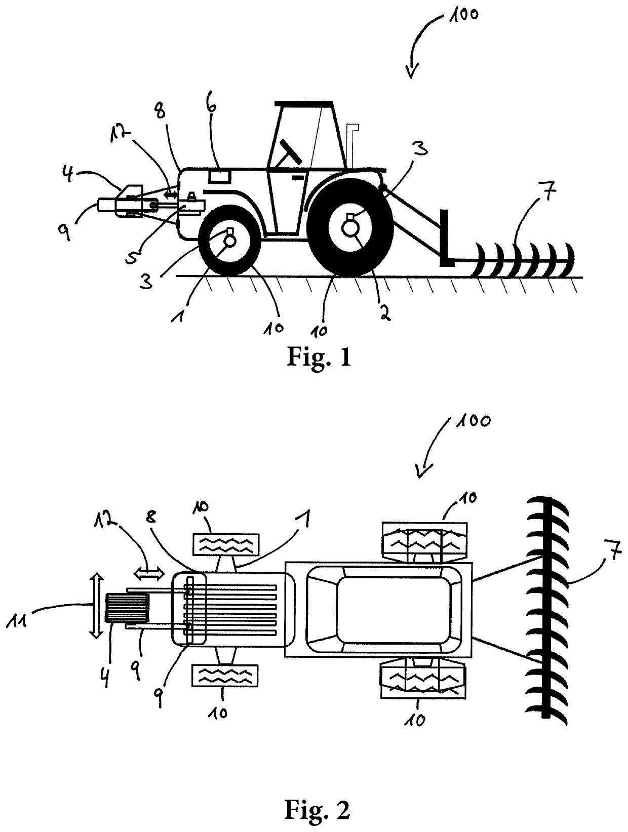
[0036]FIGS. 1 and 2 show schematically an embodiment of the presently proposed vehicle 100 in the lateral view and in the top view, respectively. The vehicle 100 is depicted as a tractor but may also be any other off-highway vehicle, in particular an agriculture or forestry vehicle such as a forage harvester, a combine harvester, a forestry machine, or the like. The vehicle 100 comprises a first axle 1 and a second axle 2 and a sensor unit 3 comprising a first load sensor configured to produce a load sensor signal indicative of a load on the first axle 1 and a second load sensor configured to produce a load sensor signal indicative of a load on the second axle 2. The two load sensors of the sensor unit 3 are configured to produce real time signals indicative of the vertical force and the horizontal force exerted on the first axle 1 and the second axle 2, respectively. The load sensors may be a force sensor or a strain sensor. The vertical force is a force in a vertical direction per...


PUM


Abstract

The present disclosure relates to a vehicle, in particular an off-highway vehicle, comprising a first axle and a second axle and a sensor unit comprising at least one load sensor configured to produce a load sensor signal indicative of a load on at least one of the first axle and the second axle. The vehicle further comprises a movable weight configured to be moved relative to the first axle and to the second axle, an actuator system configured to move the movable weight relative to the first axle and to the second axle, and a control unit configured to control the actuator system based at least on the load sensor signal.

Description

CROSS-REFERENCE TO RELATED APPLICATIONS[0001]The present application claims priority to European Application No. 19199703.0, entitled “VEHICLE AND METHOD OF CONTROLLING A LOAD DISTRIBUTION OF A VEHICLE”, and filed on Sep. 25, 2019. The entire contents of the above-listed application are hereby incorporated by reference for all purposes.TECHNICAL FIELD[0002]The present application relates to a vehicle and to a method of controlling a load distribution of a vehicle. Vehicles of the presently proposed type may be off-highway vehicles, for example agriculture or forestry vehicles such as forage harvesters, combine harvesters, tractors, or the like.BACKGROUND AND SUMMARY[0003]Off-highway vehicles such as agriculture vehicles are known for delivering high traction forces at slow speeds to complete agriculture tasks such as towing trailers, agriculture machinery, agriculture implements, or the like. Due to the variety of the agriculture tasks and the off-highway conditions, an agriculture ...

Claims


Application Information

Patent Timeline
IPC IPC(8): B62D49/08B60K28/14
CPCB62D49/085B60Y2300/02B60K28/14B62D49/0628B62D37/04
Inventor CALCAGNOTTO DA SILVA, JOSEMIRSERRAO, LORENZO
Owner DANA ITAL SRL
Why Eureka
Eureka Blog
Learn More