Water inlet valve

a technology for water inlet valves and valve bodies, applied in the direction of valve operating means/releasing devices, valve functional types, transportation and packaging, etc., can solve the problems of water tank accessories (water inlet valves, drain valves, buttons, etc., to reduce the waste of water resources

Active Publication Date: 2016-09-13
LAB XIAMEN SANITARY FITTINGS
View PDF4 Cites 6 Cited by
  • Summary
  • Abstract
  • Description
  • Claims
  • Application Information

AI Technical Summary

Benefits of technology

[0006]The primary object of the present invention is to provide a water inlet valve. Through the water inlet valve, water inflow can be stopped in time under the condition that water tank accessories and a water tank fail, so that waste of water resources is reduced.

Problems solved by technology

However, the water tank accessories (a water inlet valve, a drain valve, a button, and other sealing members) may fail after a period of time.
For example, the drain valve cannot be closed tightly to leak slowly (a leak of less water), the part of the drain valve or the button fail and are unable to close to drain all the time (a leak of much water), or the water inlet valve is unable to stop water inflow to cause an overflowing.
The aforesaid situations result in waste of water resources.

Method used


Image

  • Water inlet valve
  • Water inlet valve
  • Water inlet valve

Examples


Embodiment Construction

[0036]Embodiments of the present invention will now be described, by way of example only, with reference to the accompanying drawings.

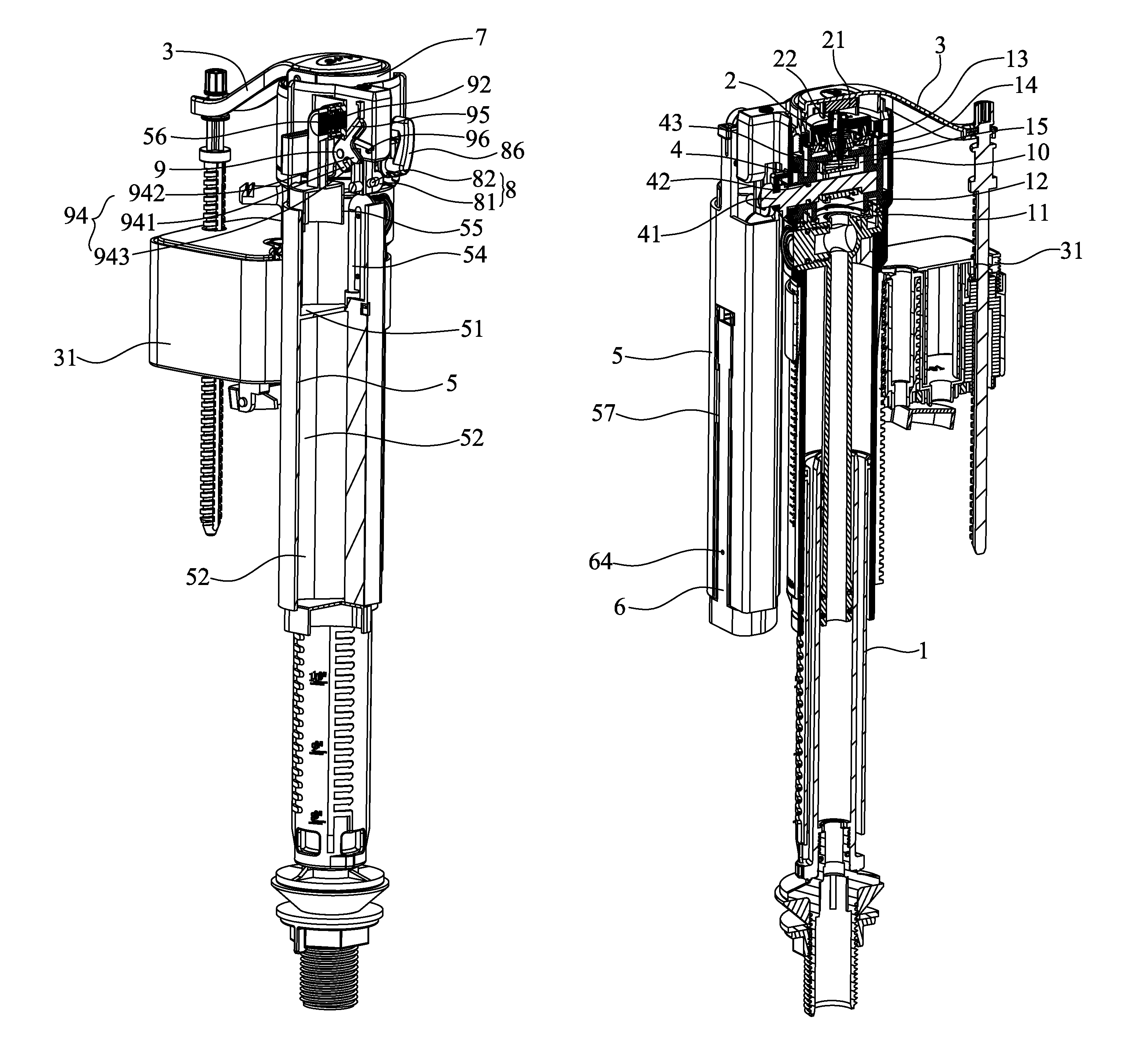
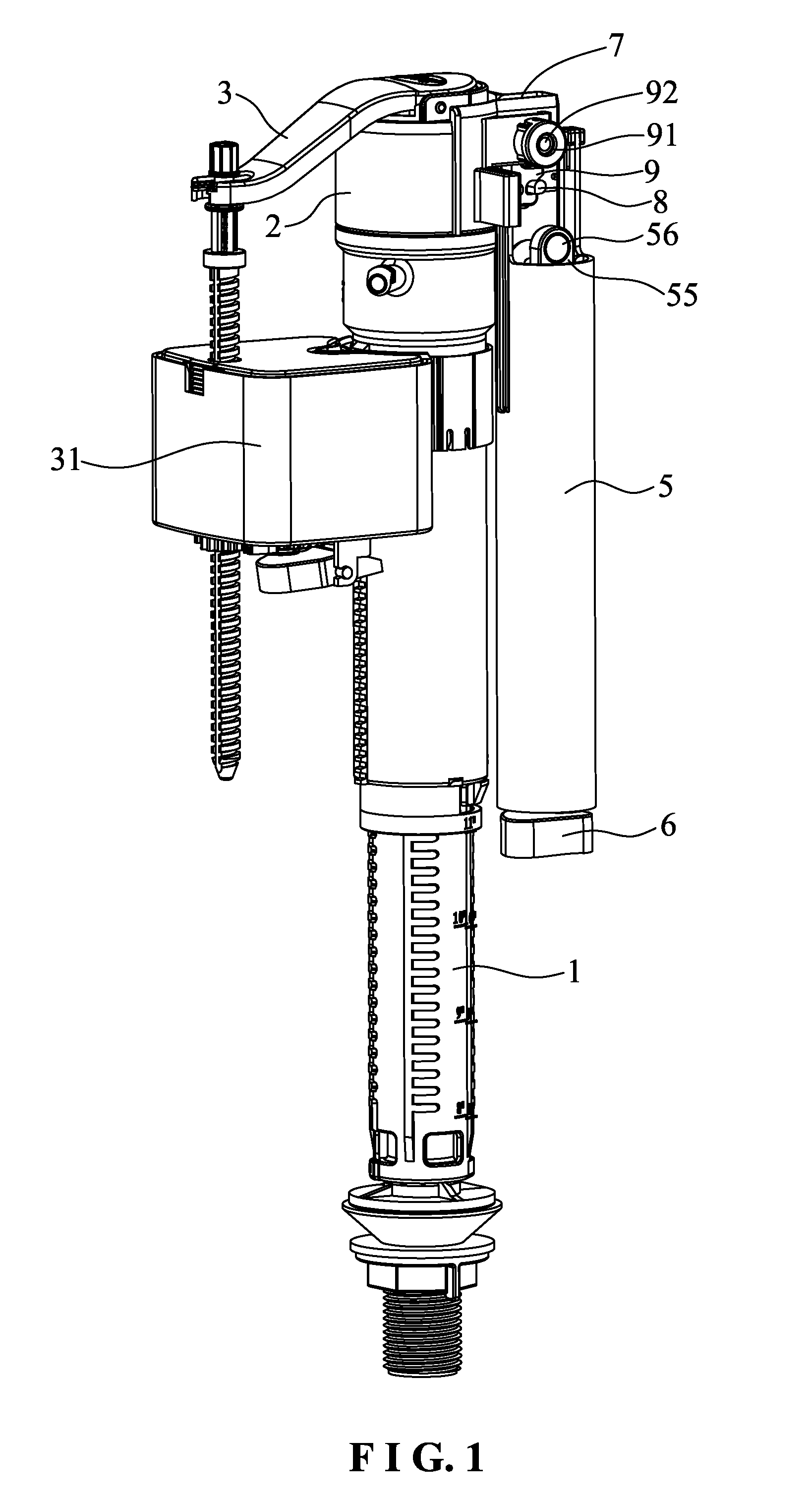
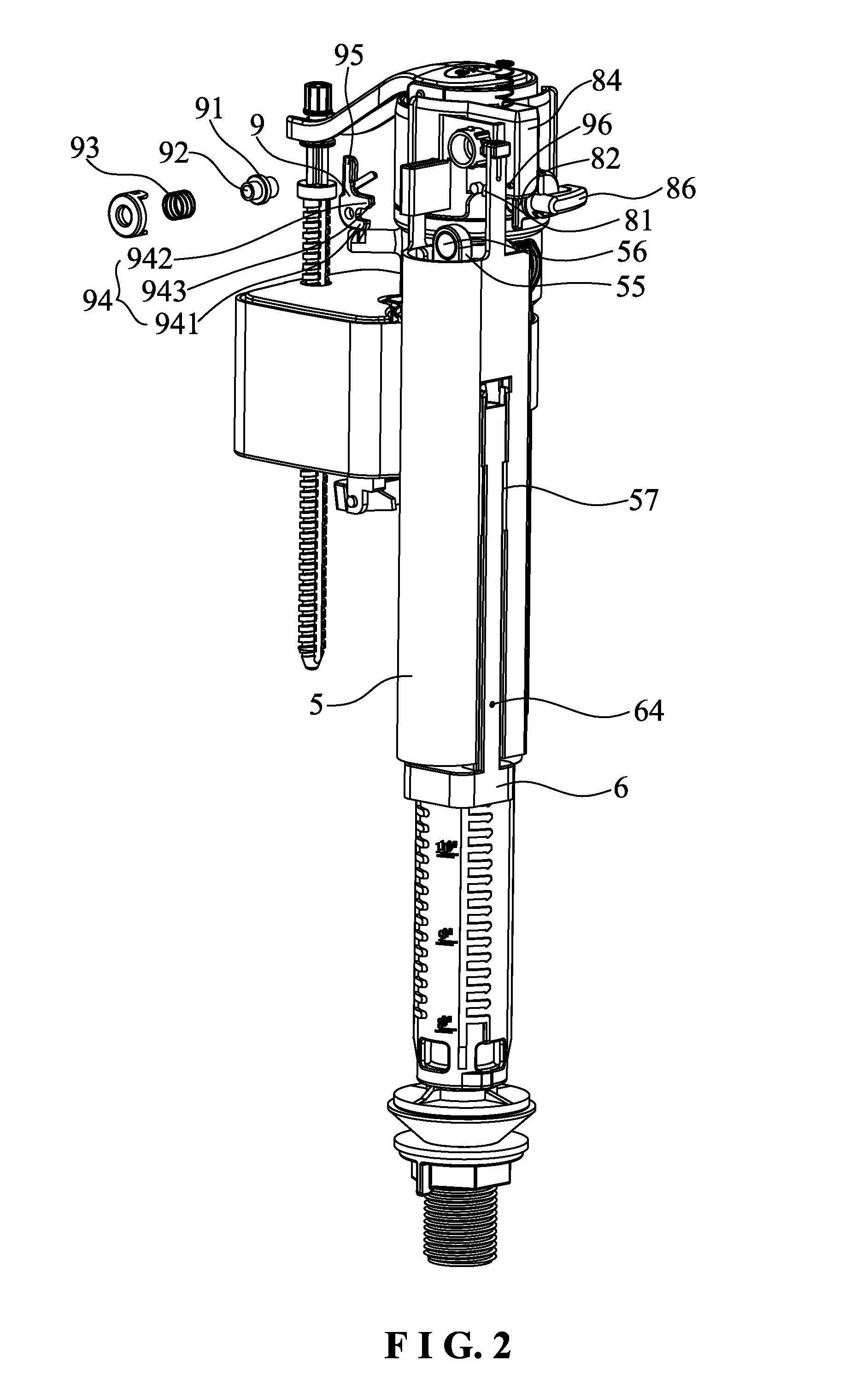
[0037]As shown in FIG. 1 and FIG. 12, the present invention disclosures a water inlet valve. The water inlet valve comprises a water inlet pipe 1, a top cover 2, a water stop pad 13, a back-pressure pad 21, a swing arm 3, and a buoy 31. This is the essential structure of an existing water inlet valve. The lower end of the water inlet pipe 1 is installed on a water supply pipe of a water tank. The top cover 2 is installed on the upper end of the water inlet pipe 1. A water inlet cavity 10 is formed by the top cover 2 and the interior of the water inlet pipe 1. The water inlet cavity 10 is formed with a water stop surface 14 having a water inlet 15. The water stop pad 13 is installed in the water inlet cavity 10, corresponding in position to the water inlet 15 and located above the water stop surface 14. The top cover 2 is formed with a back-pressure ho...


PUM


Abstract

A water inlet valve includes a water sealing piston installed in a water inlet pipe and a top cover. A water storage cylinder is fixed outside the water inlet pipe. A lower water cavity has an upper air vent and a lower water inlet. A siphon is arranged in a water storage cavity and communicated with the lower water cavity. A first magnetic element is arranged on a floater. A small buoy is arranged outside the water storage cylinder to open and close the upper air vent. A gutter is formed on the periphery of the top cover. A lever and an eccentric shaft are arranged outside the water inlet pipe and the top cover. The connecting rod is connected with the lever and the eccentric shaft. The lever is provided with an energy storage spring, a second magnetic element, and a restoring spring.

Description

BACKGROUND OF THE INVENTION[0001]1. Field of the Invention[0002]The present invention relates to a water inlet valve, and more particularly to a water inlet valve which can stop water inflow in time under the condition that water tank accessories and a water tank fail.[0003]2. Description of the Prior Art[0004]A conventional water inlet valve comprises a water inlet pipe, a top cover, a water stop pad, a back-pressure pad, a swing arm, and a buoy. The lower end of the water inlet pipe is installed on a water supply pipe of a water tank. The top cover is installed on the upper end of the water inlet pipe. The interior of the water inlet pipe is formed with a water inlet cavity. The water inlet cavity is formed with a water stop surface having a water inlet. The water stop pad is installed in the water inlet cavity, corresponding in position to the water inlet and located above the water stop surface. The top cover is formed with a back-pressure hole. The middle section of the swing a...

Claims


Application Information

Patent Timeline
Patent Type & Authority Patents(United States)
IPC IPC(8): F16K31/18E03D1/24E03D1/33E03D1/32E03D1/00E03D1/36F16K21/18
CPCE03D1/32E03D1/33F16K21/18F16K21/185Y10T137/7349Y10T137/7374Y10T137/7404Y10T137/7462Y10T137/7465
Inventor LIU, YONGMAOZHANG, ZIPENG
Owner LAB XIAMEN SANITARY FITTINGS
Why Eureka
Try Eureka