Camera body, mount adapter, and methods of controlling operation of same

a technology of mount adapter and camera body, which is applied in the field of controls the operation of the camera body and mount adapter, which can solve the problems of inability to perform captured image correction conforming to the lens, inability to receive camera information, and inability to control the lens appropriately. camera, so as to achieve the effect of comparatively easy correction of captured imag

Active Publication Date: 2016-10-11
FUJIFILM CORP
View PDF22 Cites 9 Cited by
  • Summary
  • Abstract
  • Description
  • Claims
  • Application Information

AI Technical Summary

Benefits of technology

[0011]An object of the present invention is to arrange it so that a captured image can be corrected comparatively easily in accordance with a lens mounted via a mount adapter.
[0027]The setting switch is, for example, a slide switch. In this case, the slide switch would include: a knob member freely slidable along the circumferential surface of the mount adapter and formed to have a projection penetrating into the interior of the mount adapter; a positioning member formed to have recesses conforming to direction of movement of the knob member, the recesses corresponding to the number of states settable by the setting switch; a biasing mechanism for biasing the positioning member toward an inner circumferential surface of the mount adapter; and an engaging mechanism for engaging with the interchangeable lens as a result of the interchangeable lens having been mounted on the mount adapter, and when the interchangeable lens is removed from the mount adapter, for disengaging from the interchangeable lens and disengaging the projection of the knob member from a recess of the positioning member against biasing of the positioning member by the biasing mechanism.

Problems solved by technology

When another mount lens is mounted, there are instances where the camera cannot receive lens information because of a mismatch between the communication standards of the camera and lens.
As a consequence, there are cases where the camera cannot control the lens appropriately or where a captured image correction conforming to the lens cannot be performed.
In a case where a user inputs some lens information to a camera manually, this operation can become troublesome when using multiple lenses interchangeably.
Further, Patent Documents 1 to 3 do not take into consideration the correcting of captured images in accordance with a lens mounted via a mount adapter.

Method used


Image

  • Camera body, mount adapter, and methods of controlling operation of same
  • Camera body, mount adapter, and methods of controlling operation of same
  • Camera body, mount adapter, and methods of controlling operation of same

Examples


Embodiment Construction

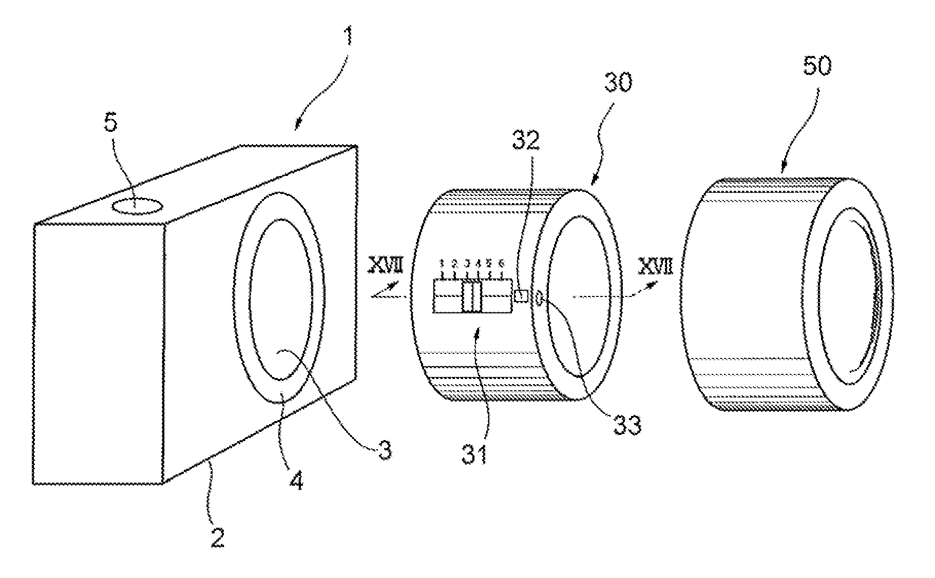
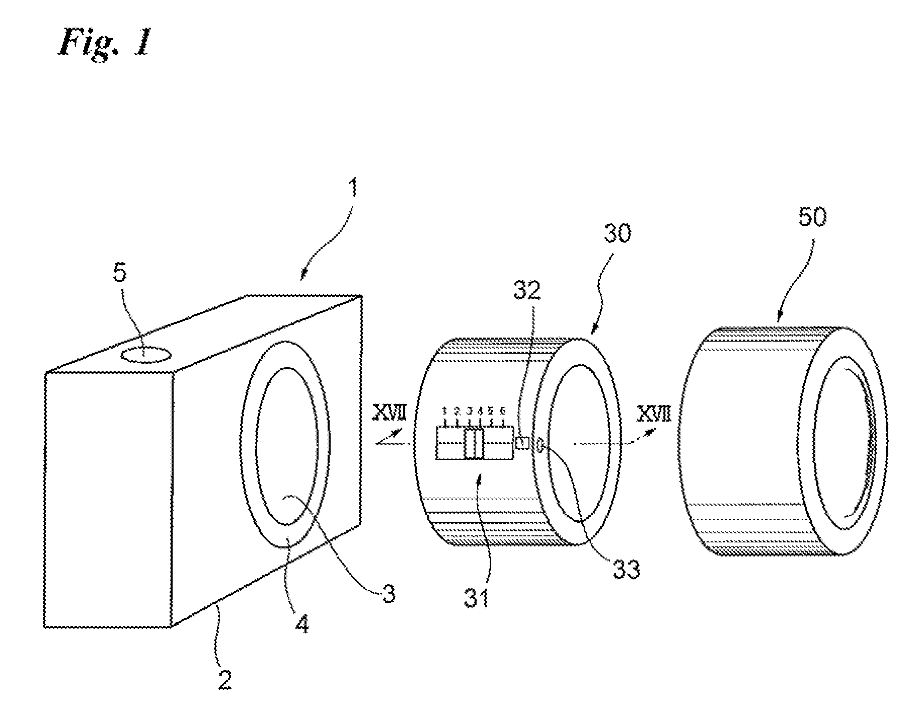
[0042]FIG. 1, which illustrates an embodiment of the present invention, is a perspective view of a camera body 1, a mount adapter 30 and an interchangeable lens 50.

[0043]The camera body 1 is of the nonreflex-type the lens of which can be interchanged. An opening 3 is formed in the front side (the right side in FIG. 1) of the camera body 1 approximately at the center thereof. The periphery of the opening 3 is formed to have a mount 4 in which the mount adapter 30 is to be mounted.

[0044]The top side of the camera body 1 is provided with a shutter-release button 5.

[0045]The mount adapter 30, which is annular in shape, is formed to have mounts 44 and 45 at respective ones of both ends thereof. The first mount 44, which is on the left side in FIG. 1, will be attached to the camera body 1, and the second mount 45, which is on the right side in FIG. 1, will be attached to the interchangeable lens 50.

[0046]A slide switch 31, which is freely slidable along the optical axis, is formed on the ...


PUM


Abstract

An image captured using a lens mounted via a mount adapter is corrected in simple fashion in accordance with the lens. An interchangeable lens is mounted on a camera body via the mount adapter. The mount adapter is provided with a slide switch capable of setting a lens type that corresponds to the interchangeable lens. The slide switch is positioned in accordance with the interchangeable lens. The switch setting state of the positioned slide switch is detected in the camera body. Correction parameters that conform to the detected switch setting state are read out of a memory within the camera body. The captured image is corrected using the correction parameters that have been read out.

Description

CROSS-REFERENCE TO RELATED APPLICATIONS[0001]This application is a Continuation of PCT International Application No. PCT JP2013 / 083835 filed on Dec. 18, 2013, which claims priority under 35 U.S.C. §119(a) to Japanese Patent Application No. 2013-057669 filed Mar. 21, 2013. Each of the above application(s) is hereby expressly incorporated by reference, in its entirety, into the present application.BACKGROUND OF THE INVENTION[0002]1. Field of the Invention[0003]This invention relates to a camera body and mount adapter as well as methods of controlling operation of the camera body and mount adapter.[0004]2. Description of the Related Art[0005]Utilizing a mount adapter makes it possible for another mount lens to be mounted on a non-reflex camera. When another mount lens is mounted, there are instances where the camera cannot receive lens information because of a mismatch between the communication standards of the camera and lens. As a consequence, there are cases where the camera cannot ...

Claims


Application Information

Patent Timeline
Patent Type & Authority Patents(United States)
IPC IPC(8): H04N5/225H04N5/357H04N5/217G03B17/14H04N5/232G03B17/18
CPCH04N5/3572H04N5/23209G03B17/14G03B17/18H04N5/217H04N5/2254H04N5/23229H04N5/23293G03B2206/00H04N23/81H04N23/55H04N23/663H04N23/633H04N23/632H04N25/61H04N25/611H04N23/80
Inventor IRIE, FUMINORI
Owner FUJIFILM CORP
Why Eureka
Try Eureka