Device for combining force among control units, control unit and aircraft

a technology of coupling device and control unit, which is applied in the direction of automatic actuation, process and machine control, instruments, etc., can solve the problems of constant effort supplied by the motor against the disadvantage of coupling device degrading the effort sensation of the pilot, and the inability to control the effort of the pilot, etc., to achieve reliable disconnection signal, increase the disconnection limit effort, and the effect of greater position differen

Active Publication Date: 2016-10-18
RATIER FIGEAC
View PDF11 Cites 2 Cited by
  • Summary
  • Abstract
  • Description
  • Claims
  • Application Information

AI Technical Summary

Benefits of technology

[0020]Advantageously and according to the invention, the predetermined threshold is variable as a function of a difference between signals representing a position of the operating handle of each piloting member. In this variant of the coupling device according to the invention, the admissible disconnection effort is then variable as a function of the difference in position between the sticks of the pilot and that of the copilot. The greater the difference in position, the higher the disconnection limit effort will be.
[0021]Advantageously and according to the invention, the correcting device further has a threshold comparator at the output of the deadband corrector adapted to supply a disconnection signal when the output of the corrector is not zero. In this way, the disconnection signal between the pilots' sticks no longer depends on the current circulating in the electric motor of the piloting member

Problems solved by technology

Such an effort coupling device has the disadvantage of degrading the effort sensations of the pilot, on simulating a connection comparable to a rigid rod between the piloting members of the pilot and the copilot.
Such a “disconnection” is not achieved in the coupling device of the prior art and a limitation of the efforts is

Method used


Image

  • Device for combining force among control units, control unit and aircraft
  • Device for combining force among control units, control unit and aircraft
  • Device for combining force among control units, control unit and aircraft

Examples


first embodiment

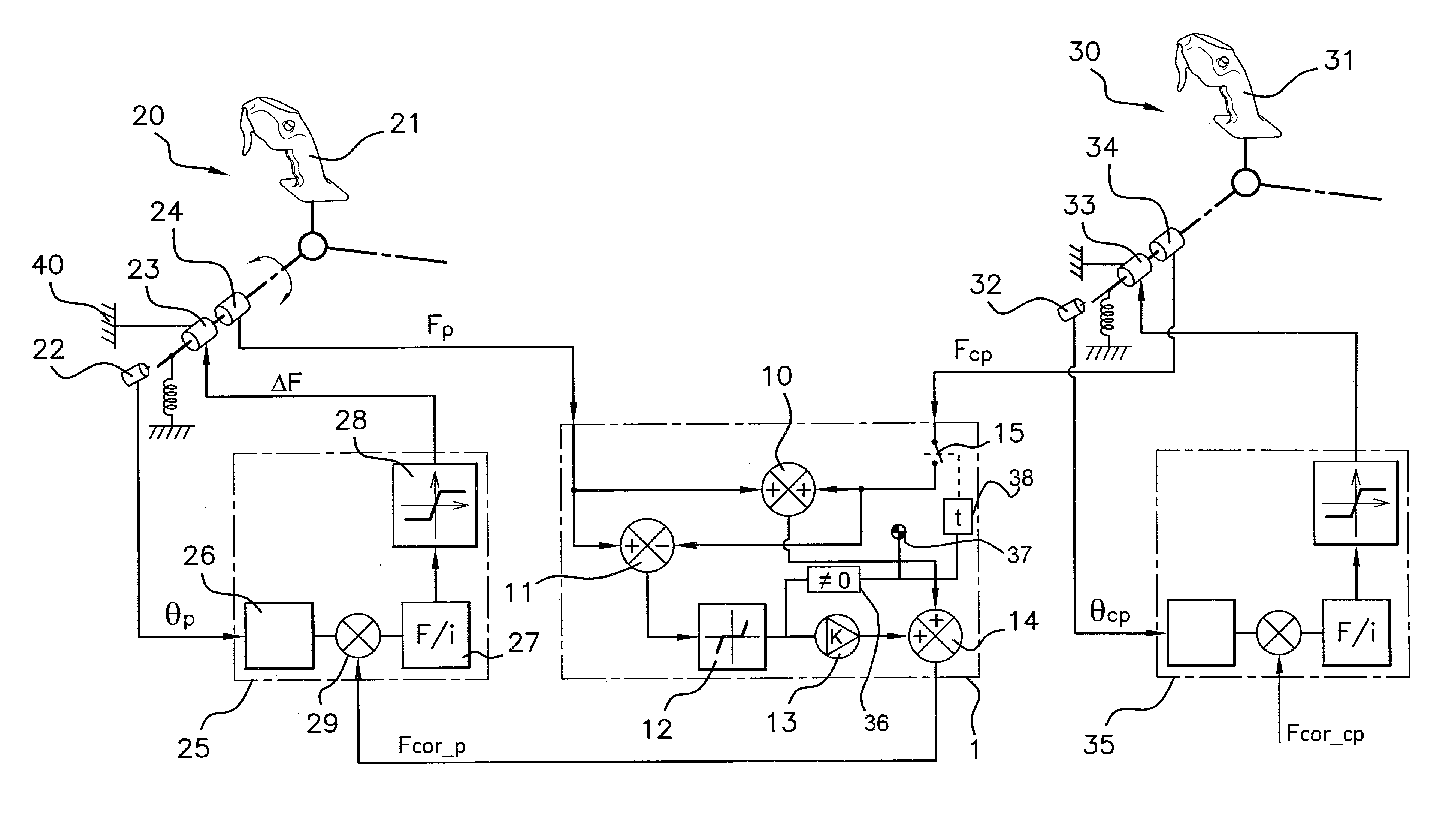
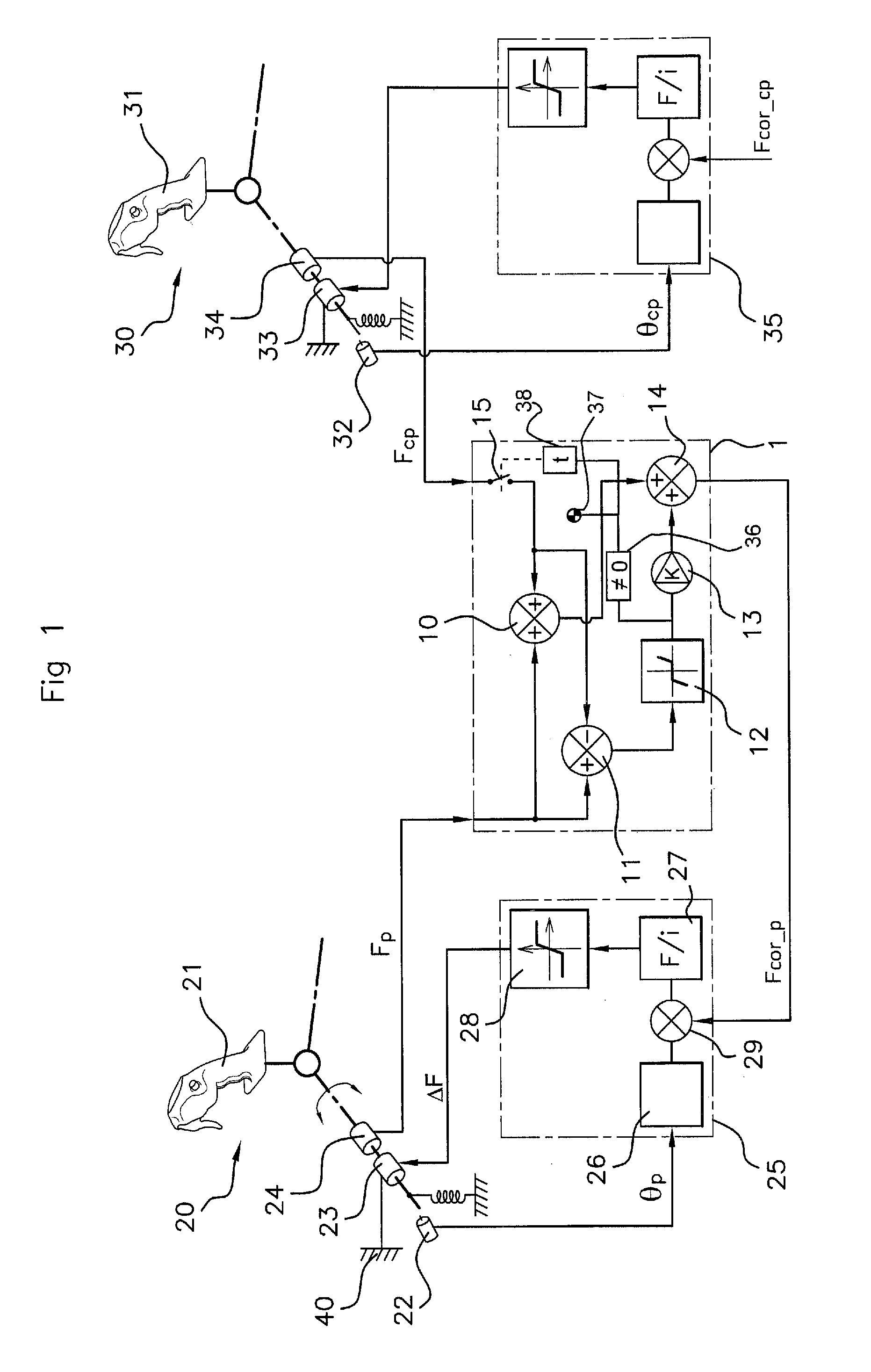
[0049]In the invention, the effort coupling device 1, associated with the mini-stick 20, works out the effort feedback value Fcor_p from the piloting efforts Fp and Fcp coming respectively from the torque sensor 24 of the mini-stick 20 of the pilot and the torque sensor 34 of the mini-stick 30 of the copilot. A summer 10 performs the sum Fp+Fcp and transmits it to a second summer 14.

[0050]The piloting efforts Fp and Fcp are also transmitted to a comparator 11 adapted to obtain the difference between the values of these piloting efforts. The output of the comparator 11 is then transmitted to a deadband corrector 12. The transfer function of this corrector 12 will be better understood in conjunction with the graph of FIG. 3. The difference Fp−Fcp is represented as the abscissa of the graph of FIG. 3 and the output of the corrector 12 corresponds to the ordinate of this graph. The deadband of the corrector 12 extends between a negative threshold −2Flim and a positive threshold +2Flim, ...

second embodiment

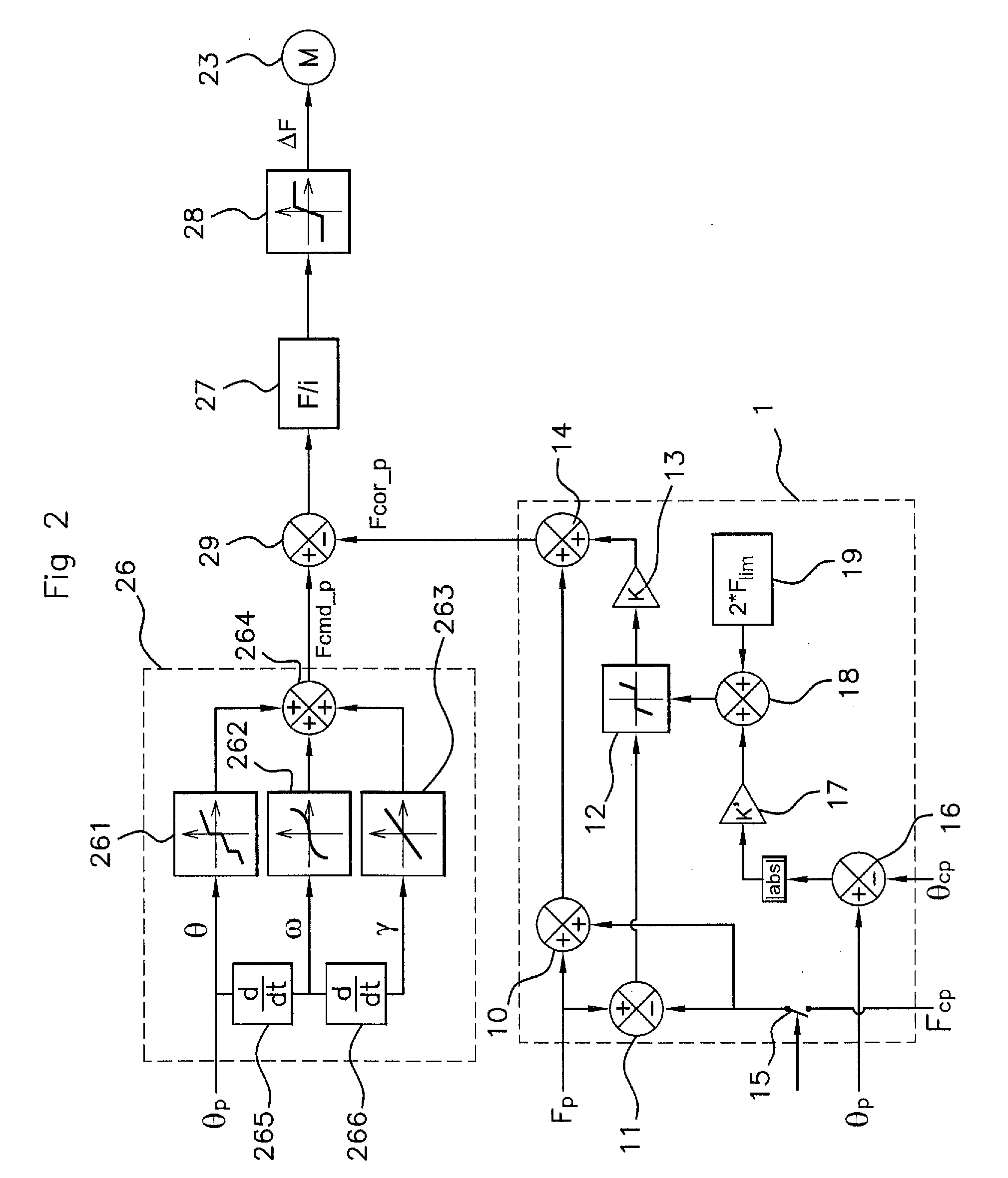
[0072]In the effort coupling device 1 according to the invention, illustrated in FIG. 4, the device 1 has an effort saturator 41 in series between the input of the piloting effort Fcp of the copilot and the summer 10. The effort saturator 41 has limit values provided for limiting the value of the piloting effort Fcp to a value corresponding to the value Flim of the admissible disconnection effort. Thus, the effort feedback Fcor_p is equal to Fp+Fcp if Fcp is less than Flim, or equal to Fp+Flim if Fcp is greater than Flim.

[0073]The effort coupling device 1 further comprises, at the terminals of the saturator 41 and in parallel with the latter, a comparator 11′ adapted to obtain the difference between the output of the saturator 41 and the piloting effort Fcp at the input of the latter. This difference is zero if the piloting effort Fcp is less than Flim. This difference is supplied to the threshold comparator 36 for generating the disconnection signal suitable for driving the disconn...


PUM


Abstract

A device for combining force between two control units includes force feedback, each control unit including a control stick (21, 31) and at least one force sensor (24, 34) suitable for providing a value of the control force (Fp, Fcp) exerted by a pilot, the device being suitable for forming a force feedback value from the sum of the values of the control forces of each control unit. A correction device limits the force feedback value (Fcor_p) according to at least one parameter taken from the absolute value of the control force (Fcp) of the second control unit and the difference between the control force values of each control unit. A control unit including such a device for combining forces, and an aircraft provided with such control units are also described.

Description

BACKGROUND OF THE INVENTION[0001]1. Field of the Invention[0002]The invention relates to an effort coupling device for effort coupling between at least two piloting members of an aircraft comprising a piloting device equipped, for each flying member of the aircraft, with two such piloting members connected (by a completely mechanical kinematic chain or at least partly electrically) to this flying member, so that the aircraft can be piloted simultaneously by two people: a captain (or pilot) and a copilot.[0003]Throughout the text, the term “piloting” and its derivatives denote, unless otherwise stated, the flying of an aircraft by at least one human pilot operating at least one piloting member such as a stick, handle, rudder bar, pedal, etc., connected to at least one flying member such as a control surface or a throttle control of the aircraft. Furthermore, the term “effort” is employed to denote equally well a torque or a force, according to the arrangement on which this effort is ...

Claims


Application Information

Patent Timeline
IPC IPC(8): B64C13/16B64C13/12G05D1/00B64C13/04
CPCB64C13/16B64C13/04B64C13/12G05D1/0077B64C13/507B64C13/0421B64C13/10
Inventor ANTRAYGUE, CEDRIC
Owner RATIER FIGEAC
Why Eureka
Try Eureka