Detachable electric wheelchair

a wheelchair and electric technology, applied in wheelchairs/patient conveyances, medical transportation, ambulance services, etc., can solve the problems of heavy weight of electric power devices difficult and the electric power device of conventional electric wheelchairs is not easy to be detached or folded

Active Publication Date: 2016-10-25
CHAN SHU CHEN
View PDF4 Cites 16 Cited by
  • Summary
  • Abstract
  • Description
  • Claims
  • Application Information

AI Technical Summary

Benefits of technology

[0007]The electric wheelchair has a chair, an electrical power device, a foot stand, and a control device. The chair is foldable and has a seat, a back rest, two arm rest frames, two front wheels, and two pushing bars. The seat has two sides. The back rest is foldable, is connected with the seat, and has two sides. The arm rest frames are respectively connected securely with the sides of the seat. Each arm rest frame has a connection board provided with multiple connecting holes defined in the connection board. The front wheels are respectively mounted rotatably on the arm rest frames. The pushing bars are connected respectively with the arm rest frames and are located respectively at the sides of the back rest. The electrical power device is detachably connected with the chair between the arm rest frames and has a holding frame, a driving device, and two rear wheels. The holding frame is connected detachably with the arm rest frames and has two sides and two holding boards. The holding boards are mounted respectively on the sides of the holding frame and are respectively connected with the connection boards of the arm rest frames by multiple securing assemblies. Each securing assembly has a holding sleeve, a c...

Problems solved by technology

However, the electric power device of the conventional electric wheelchair has a heavy weight and is not easy to be detached or fold...

Method used


Image

  • Detachable electric wheelchair
  • Detachable electric wheelchair
  • Detachable electric wheelchair

Examples


Embodiment Construction

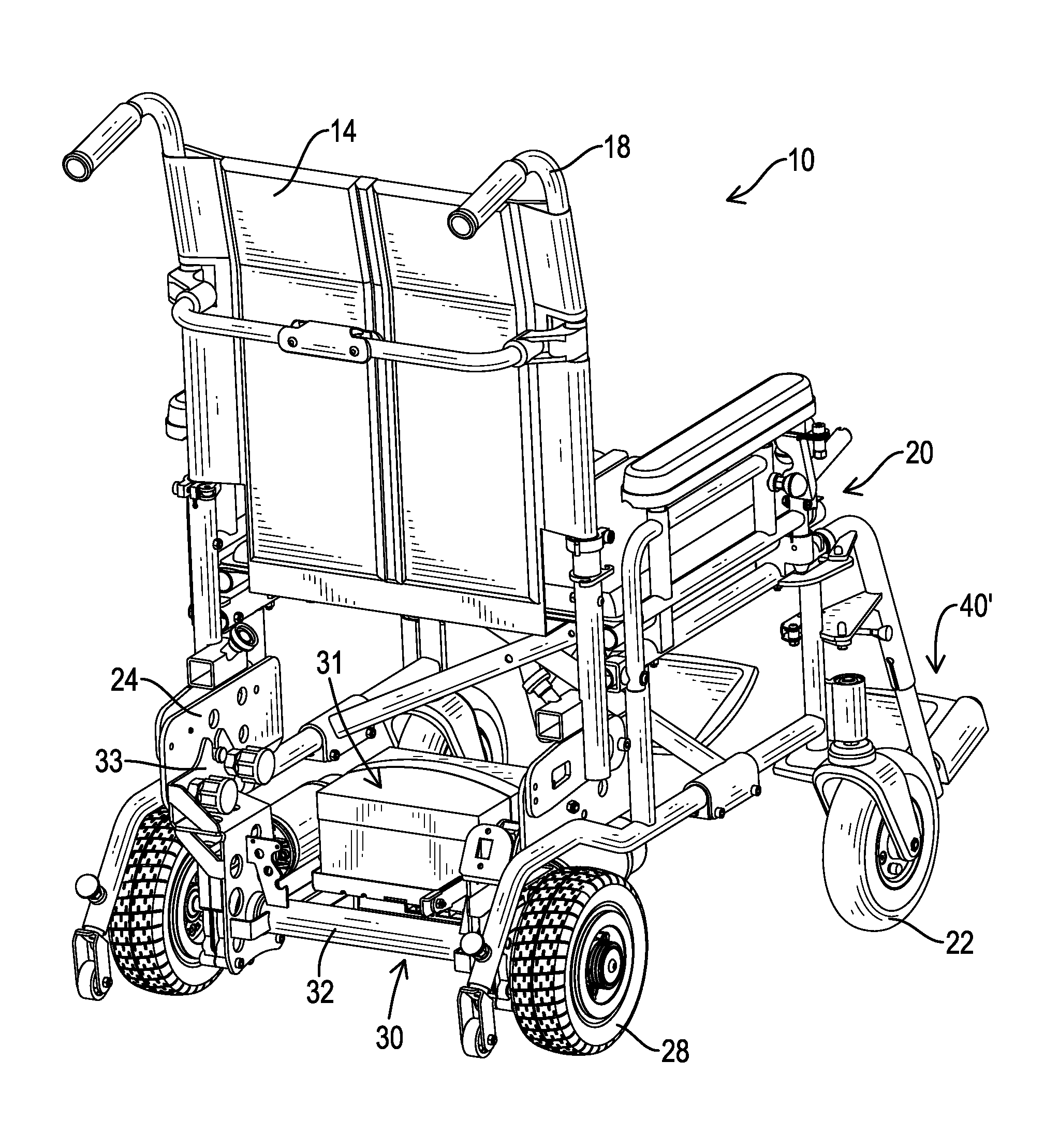
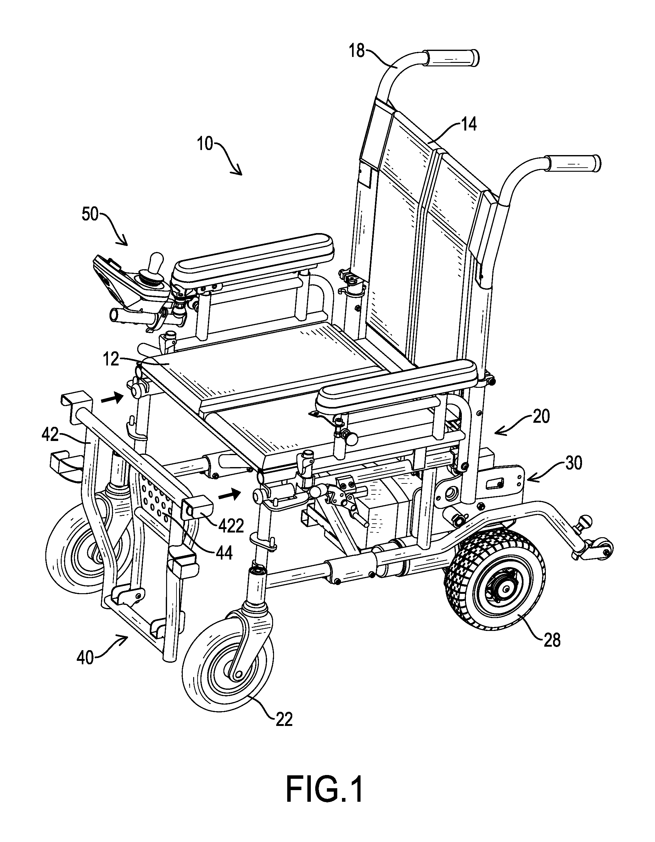
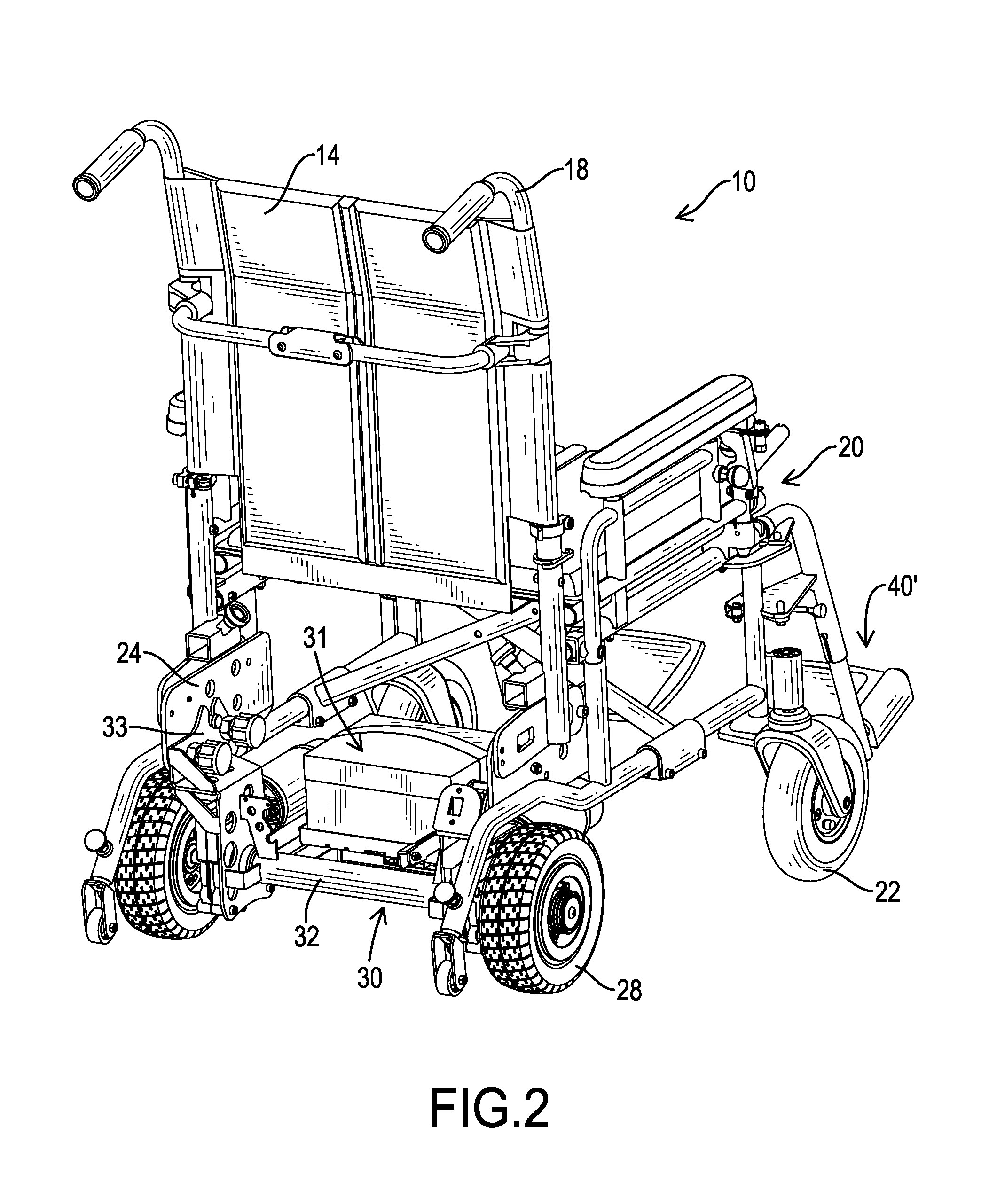
[0025]With reference to FIGS. 1 and 2, an electric wheelchair in accordance with the present invention comprises a chair 10, an electrical power device 30, a foot stand 40, and a control device 50. The chair 10 is foldable and comprises a seat 12, a back rest 14, two arm rest frames 20, two front wheels 22, and two pushing bars 18. The seat 12 is foldable and has two sides. The back rest 14 is foldable, is connected with the seat 12, and has two sides. The arm rest frames 20 are respectively connected securely with the sides of the seat 12. Each arm rest frame 20 is composed of multiple rods and has an arm rest to allow a hand of a user to put on the arm rest and a connection board 24. The connection board 24 is provided with multiple connecting holes 242 defined in the connection board 24. The front wheels 22 are respectively mounted rotatably on the arm rest frames 20. The pushing bars 18 are connected respectively with the arm rest frames 20 and are located respectively at the si...


PUM


Abstract

A wheelchair has a chair, an electrical power device, a foot stand, and a control device. The chair has two arm rest frames, and each arm rest frame has a connection board. The electrical power device is detachably connected with the connection boards and has a holding frame, a driving device, and two rear wheels. The holding frame has two holding boards respectively connected with the connection boards by multiple securing assemblies. Each securing assembly has a holding sleeve, a connecting rod, a knob, and a spring. The holding sleeve has multiple abutting ribs. The connecting rod is mounted through the holding sleeve and has a first end and a second end selectively extending into one of the connecting holes defined in a corresponding connection board. The knob is mounted securely around the second end of the connecting rod and has multiple engaging grooves.

Description

BACKGROUND OF THE INVENTION[0001]1. Field of the Invention[0002]The present invention relates to an electric wheelchair, and more particularly to a detachable and foldable electric wheelchair.[0003]2. Description of Related Art[0004]A wheelchair is applied to assist a person in need of mobility aid. A conventional wheelchair has two different types including a manual type and an electric type. The conventional electric wheelchair is driven by electric power and is convenient to transport people in need of mobility aid to desired locations. The conventional electric wheelchair comprises an electric power device having a motor and a battery. However, the electric power device of the conventional electric wheelchair has a heavy weight and is not easy to be detached or folded. Therefore, the conventional electric wheelchair can hardly be transported to another location by vehicles and is not convenient in use.[0005]To overcome the shortcomings, the present invention tends to provide an ...

Claims


Application Information

Patent Timeline
IPC IPC(8): A61G5/04A61G5/08A61G5/12
CPCA61G5/047A61G5/08A61G2005/125A61G2005/122A61G2005/128A61G5/125A61G5/128A61G5/0825A61G5/0883
Inventor CHAN, SHU-CHEN
Owner CHAN SHU CHEN
Why Eureka
Try Eureka