Supercharge Your Innovation With Domain-Expert AI Agents!

Delayed release restraint system

a technology of delayed release and restraints, which is applied in adaptive control, process and machine control, instruments, etc., can solve the problems of patient falls, poor balance, and decreased deficit awareness in healthcare facilities, and achieves the effects of reducing deficit awareness, impulsivity, and poor balan

Active Publication Date: 2016-11-01
UNIV OF MARYLAND
View PDF5 Cites 1 Cited by
  • Summary
  • Abstract
  • Description
  • Claims
  • Application Information

AI Technical Summary

Benefits of technology

This patent describes a delayed release restraint system that has several advantages over previously available systems. The system includes a restraining strap, latch, and delayed release apparatus. The delayed release apparatus has a first module, actuator, and second module. The first module causes the latch to open when the actuator is engaged. The second module causes the first module to open the latch after a delay of time. The system can also open the latch when a signal is received indicating an emergency evacuation. Other aspects of the invention include a method for determining the release time based on the first signal, and computer-readable media for performing the method. Overall, the system provides improved safety and reliability as a fall prevention system and a call bell system.

Problems solved by technology

Patient falls are a major problem in healthcare facilities.
These conditions can lead to poor balance, decreased deficit awareness, and impulsivity.
Even when a patient requests assistance from the medical staff, their delayed response time has been identified as a major cause of patients getting out of bed unassisted.
This poses a potential safety hazard to the patient in emergency situations.
It can also unreasonably limit their autonomy if the staff fails to attend to them within a reasonable time.
Many state laws only allow for the use of restraints if they are absolutely necessary to protect the patient or others from injury and less restrictive alternatives prove inadequate.
This can mean that a patient must get out of bed and fall before the patient is placed in lockable restraints.
These sensors serve a limited role in preventing falls because the staff is not alerted until after the patient has gotten up.

Method used


Image

  • Delayed release restraint system
  • Delayed release restraint system
  • Delayed release restraint system

Examples


Embodiment Construction

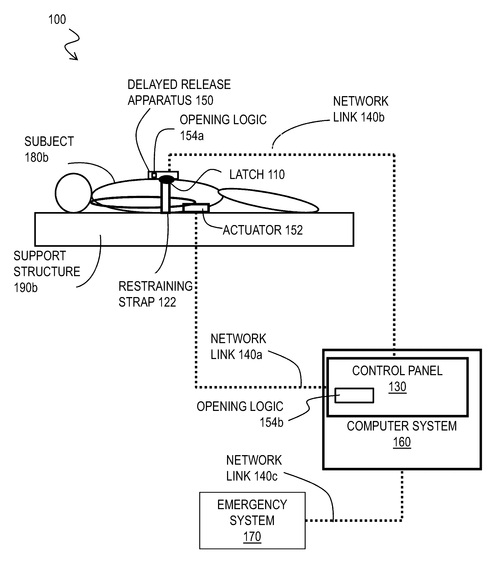
[0023]A method, apparatus and system are described for a delayed release restraint. In the following description, for the purposes of explanation, numerous specific details are set forth in order to provide a thorough understanding of the present invention. It will be apparent, however, to one skilled in the art that the present invention may be practiced without these specific details. In other instances, well-known structures and devices are shown in block diagram form in order to avoid unnecessarily obscuring the present invention.

[0024]Some embodiments of the invention are described below in the context of a patient restraint system. However, it should be understood that that this restraint system may be used in a wide range of applications requiring a variable delayed release restraint system. These may include for example, subjects which are prison inmates or livestock. Also, many embodiments are described which exclusively use electronic components; but, in other embodiments,...


PUM


Abstract

A restraint method, apparatus and system includes one or more of a restraining strap, a latch and an opening apparatus. The restraining strap is configured to bind a subject to a support structure. The latch is configured to removably engage at least one of two ends of the restraining strap. The opening apparatus includes a first module configured to cause the latch to open, an actuator, and a second module. The second module is configured to cause the first module to open the latch in response to operation of the actuator after a delay of time past the operation of the actuator. The opening module is arranged so that the subject can operate the actuator.

Description

CROSS-REFERENCE TO RELATED APPLICATIONS[0001]This application claims benefit of Provisional Application No. 61 / 616,595, filed Mar. 28, 2012, the entire contents of which are hereby incorporated by reference as if fully set forth herein, under 35 U.S.C. §119(e).BACKGROUND OF THE INVENTION[0002]Patient falls are a major problem in healthcare facilities. Patients can be confused from post-operative delirium, medical illness, dementia, or brain injury. These conditions can lead to poor balance, decreased deficit awareness, and impulsivity. Patients will often try to get out of bed without requesting assistance from the medical staff. Even when a patient requests assistance from the medical staff, their delayed response time has been identified as a major cause of patients getting out of bed unassisted.[0003]One way to prevent these injuries is to restrain the patient. Currently, there are two general classes of restraints available. The first class secures the person, but the person can...

Claims


Application Information

Patent Timeline
Patent Type & Authority Patents(United States)
IPC IPC(8): G01M1/38A61F5/37A44B11/00G08B21/00B61D3/18A44B17/00A44B11/25A44B1/04G05D23/00G05B15/00G05B13/00
CPCA44B11/005A61F5/3776Y10T24/2194
Inventor MAKLEY, MICHAEL
Owner UNIV OF MARYLAND
Features
  • R&D
  • Intellectual Property
  • Life Sciences
  • Materials
  • Tech Scout
  • Unparalleled Data Quality
  • Higher Quality Content
  • 60% Fewer Hallucinations
Learn More