Sling recoiling gun stock

a recoiling and gun stock technology, applied in the direction of weapons, butts, weapon components, etc., can solve the problems of insufficient facilitation and inefficient special-purpose firearms, and achieve the effect of facilitating gun stock lengthening or shortening

Active Publication Date: 2016-11-08
GREENWOOD TIMOTHY L
View PDF27 Cites 1 Cited by
  • Summary
  • Abstract
  • Description
  • Claims
  • Application Information

AI Technical Summary

Benefits of technology

[0006]A first structural component of the instant inventive sling recoiling gun stock comprises a hollow bored recoil buffer tube receiving sleeve. In a preferred embodiment, such sleeve component is closely fitted for nestingly and slidably receiving a recoil suppression tube of the type which commonly extends rearwardly from the breach of a modern tactical rifle or shotgun. Other modern tactical rifles present a tubular rearward extension which functions only for gun stock mounting. For purposes herein, all such rearward tubular extensions are considered to be a recoil buffer tube. Upon sliding receipt of such recoil buffer tube, the instant invention's sleeve component advantageously functions as a fastener component analogously with the socket of a common pin and socket joint. Longitudinal telescoping motion of the instant invention's sleeve with respect to such firearm recoil buffer tube advantageously facilitates gun stock lengthening or shortening for proper rear gunsight positioning upon shouldering of the weapon. The sleeve component of the invention preferably presents an undersurface which allows the sleeve to further function as an upper spool housing wall.
[0007]A further structural component of the inventive gun stock comprises a butt plate which presents a rearwardly or breachwardly facing shoulder contact land. The upper or heel end of the butt plate is preferably fixedly attached to the rearward or breachward end of the recoil buffer tube receiving sleeve. Such butt plate attachment and extension advantageously allows the butt plate to further function as a rearward spool housing wall.
[0011]Releasable fastening means suitably comprising a “D” loop engaging clip may be fixedly attached to the extreme distal end of the sling component. In a preferred embodiment, such fastening means may comprise a quick attach / detach sling clip of the type disclosed in U.S. Pat. No. 8,898,949, entitled “Firearm Tactical Rail Mounting Bracket” and issued Dec. 2, 2014, to Greenwood. Where such releasable fastening means are incorporated as a component of the inventive gun stock, the body of the fastener may advantageously further function as a retraction stop and as an easily gripable handle for drawing the spooled gun sling from the gun stock. Where such Greenwood '949 type releasable fastening means are provided, a short length of picatinny rail may be advantageously mounted to the undersurface of the stock for engaging and securely holding such clip directly beneath the gun stock.
[0015]In operation of the instant inventive gun stock, a rifleman may initially manipulate the pawl and actuator combination to disengage the pawl from the spool's lugs and recesses. Upon such disengagement, and in the absence of application of a pulling force to the sling, the preferably provided spring configured retracting means normally recoils and retracts the gun sling into the interior of the housing. The rifleman's subsequent release of the actuator advantageously allows the preferably provided pawl spring to re-engage or lock the pawl against the spool, such engagement securing the gun sling at a desired loop extension. In the event the rifleman wishes to configure the weapon to include lengthened gun sling loop, steps outlined above may be reversed while such operator pulls the gun sling outwardly from the stock. Thereafter, a release of the pawl and actuator combination's actuator advantageously secures the gun sling at a newly selected extension and length. Upon such extension to a desired sling length, the preferably provided releasable attaching means mounted at the distal end of the gun sling may be securely mounted at an attaching point upon the shoulder stock or at a forward location such as the weapon's forestock.

Problems solved by technology

Such specially modified firearms typically inefficiently and insufficiently facilitate selective gun sling extension and deployment, sling locking, and sling releasing functions which are needed in use of modern tactical rifles.

Method used


Image

  • Sling recoiling gun stock
  • Sling recoiling gun stock
  • Sling recoiling gun stock

Examples


Embodiment Construction

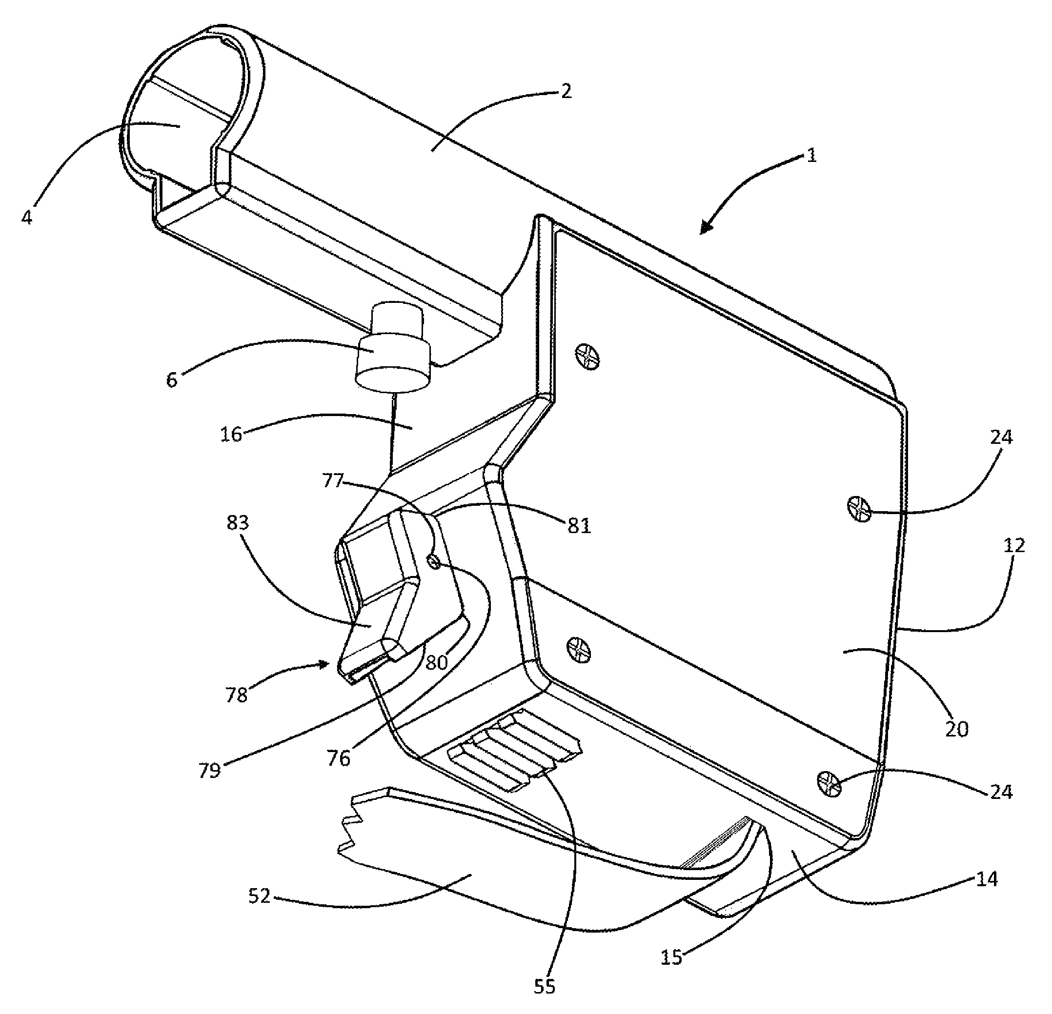
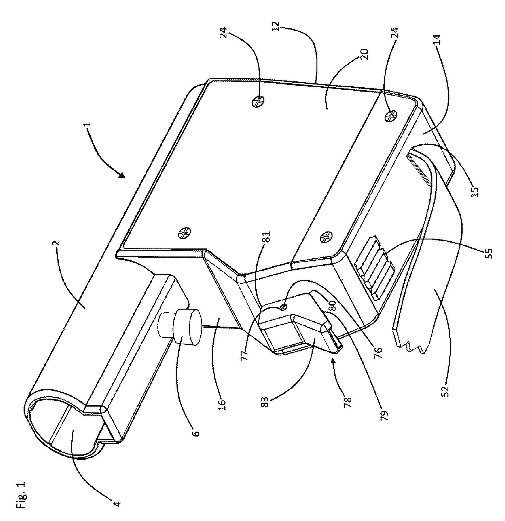
[0023]Referring now to the drawings, and in particular to Drawing FIG. 1, a preferred embodiment of the instant inventive gun sling recoiling shoulder or butt stock is referred to generally by Reference Arrow 1. The stock 1 incorporates as a major structural support component an upper tubular or cylindrical sleeve 2 having a forwardly or muzzlewardly opening hollow bore 4. In a preferred embodiment, the hollow bore 4 is fitted for slidable and telescoping mounting over the breachwardly extending recoil buffer tube (not depicted within views) of a tactical rifle or a tactical shotgun. Alternatively, the bore 4 may be fitted for receipt of a tubular stock mount, which for purposes herein is considered to constitute a recoil buffer tube. A spring biased pull pin 6 is preferably provided for selectively locking and allowing longitudinal repositioning of the gun stock 1 to a desired breachward extension from the rear gun sight of such tactical weapon.

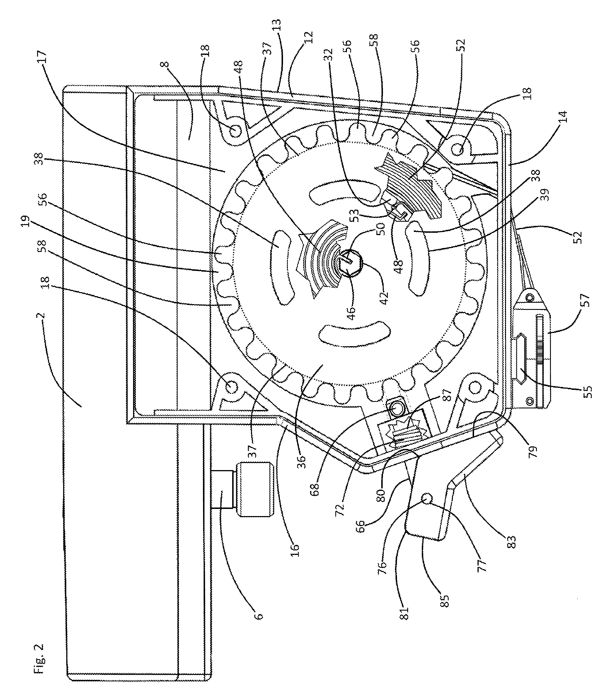
[0024]Referring simultaneously to FIG...


PUM


Abstract

A gun stock incorporating a buffer tube sleeve; a butt plate extending from the buffer tube sleeve; a spool housing attached to and extending downwardly from the buffer tube sleeve; a spool and axle combination operatively mounted within the housing; a sling having proximal end fixedly attached to the spool; a recoil spring connected operatively to the spool for drawing the sling toward the spool; multiplicities of lugs and recesses, each recess being bounded by a pair of the lugs and the recesses and lugs being formed wholly with the spool; and a pawl and pawl actuator attached to the frame, the actuator being adapted for normally engaging the pawl within at least one of the recesses.

Description

FIELD OF THE INVENTION[0001]This invention relates to tactical rifles and tactical shotguns. More particularly, this invention relates to modifications of the shoulder stocks of such as weapons for alternatively storing and deploying the weapon's gun sling.BACKGROUND OF THE INVENTION[0002]References herein to guns and rifles are intended as generally referring to and describing tactical rifles and carbines, and tactical shotguns.[0003]Hunting rifles having a sling dispensing spool which is rotatably mounted within the rear shoulder stock are known. For example, see U.S. Pat. No. 2,614,355 entitled “Retractable Sling for Guns,” issued Oct. 21, 1952, to Rogers, et al. Such specially modified firearms typically inefficiently and insufficiently facilitate selective gun sling extension and deployment, sling locking, and sling releasing functions which are needed in use of modern tactical rifles.[0004]Common modes of use of modern tactical rifles variably position the weapon at or over a ...

Claims


Application Information

Patent Timeline
Patent Type & Authority Patents(United States)
IPC IPC(8): F41C23/02F41C23/04F41C23/22
CPCF41C23/02F41C23/04F41C23/22
Inventor GREENWOOD, TIMOTHY L
Owner GREENWOOD TIMOTHY L
Why Eureka
Try Eureka