Ventilation system with a rotatable air flow generator and one or more movable registers and method for obtaining ventilation through the ventilation system

a technology of air flow generator and register, which is applied in the field of ventilation system, can solve the problems of not being very stable and reliable, the energy consumption of generating an air flow in the secondary direction may be twice as high as the energy consumption of generating a similar air flow, and the complexity of the register system

Active Publication Date: 2016-11-15
INVENTILATE APS
View PDF10 Cites 1 Cited by
  • Summary
  • Abstract
  • Description
  • Claims
  • Application Information

AI Technical Summary

Benefits of technology

[0010]Such a configuration allows for a very compact and at the same time very flexible ventilation system.
[0018]Rotating the air flow generator and moving the one or more registers simultaneously and, especially, making sure that when the air flow generator is in a given rotational position, the one or more registers are always in the same positions, allows for a safer and more reproducible control of the ventilation system.
[0022]Combining the rotational position of the air flow generator and the positions of the one or more registers as described above assures that the maximum possible air flow as well as no air flow at all through the continuous duct can be obtained.
[0026]Such a configuration ensures a mechanically simple and reliable embodiment of the ventilation system.
[0037]controlling the positions of the one or more registers, thereby controlling the opening of the air passage through the duct, so as to obtain the desired ventilation effect.

Problems solved by technology

However, such register systems may be rather complicated and they are often not very stable and reliable as seen from a mechanically point of view.
However, such air flow generators typically have a primary and a secondary air flow direction, and the energy consumption for generating an air flow in the secondary direction may be twice as high as the energy consumption for generating a similar air flow in the primary direction.
If the air flow generator is constructed to be “symmetric”, when it comes to generating air flows in the two directions, the efficiency of the air flow generator is typically rather poor in both directions.
Another problem of heat recovery systems known in the art is that the wind may force air inwards through the system, thus creating an air flow through the system, even in the opposite direction of the working direction of a weak air flow generator, if the pressure exerted by the wind exceeds the maximum possible working pressure of the air flow generator.

Method used


Image

  • Ventilation system with a rotatable air flow generator and one or more movable registers and method for obtaining ventilation through the ventilation system
  • Ventilation system with a rotatable air flow generator and one or more movable registers and method for obtaining ventilation through the ventilation system
  • Ventilation system with a rotatable air flow generator and one or more movable registers and method for obtaining ventilation through the ventilation system

Examples


Embodiment Construction

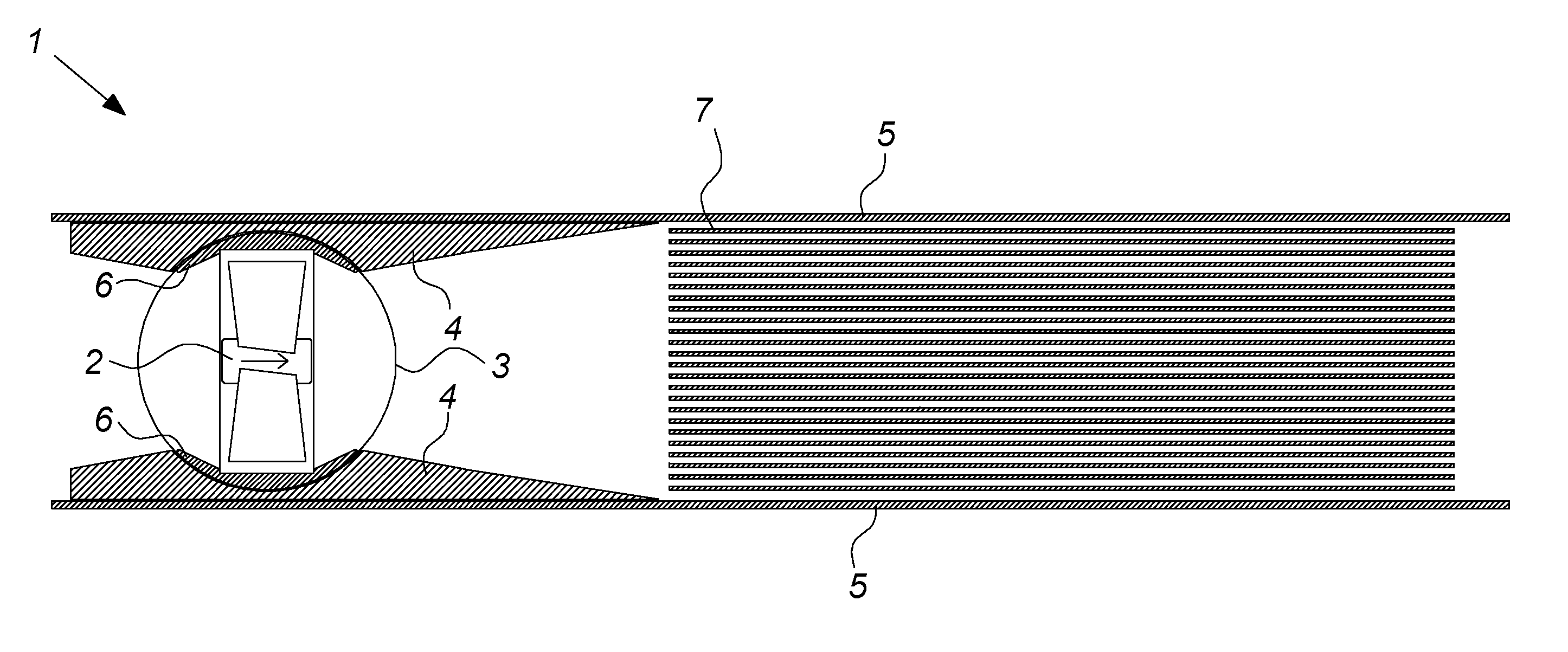
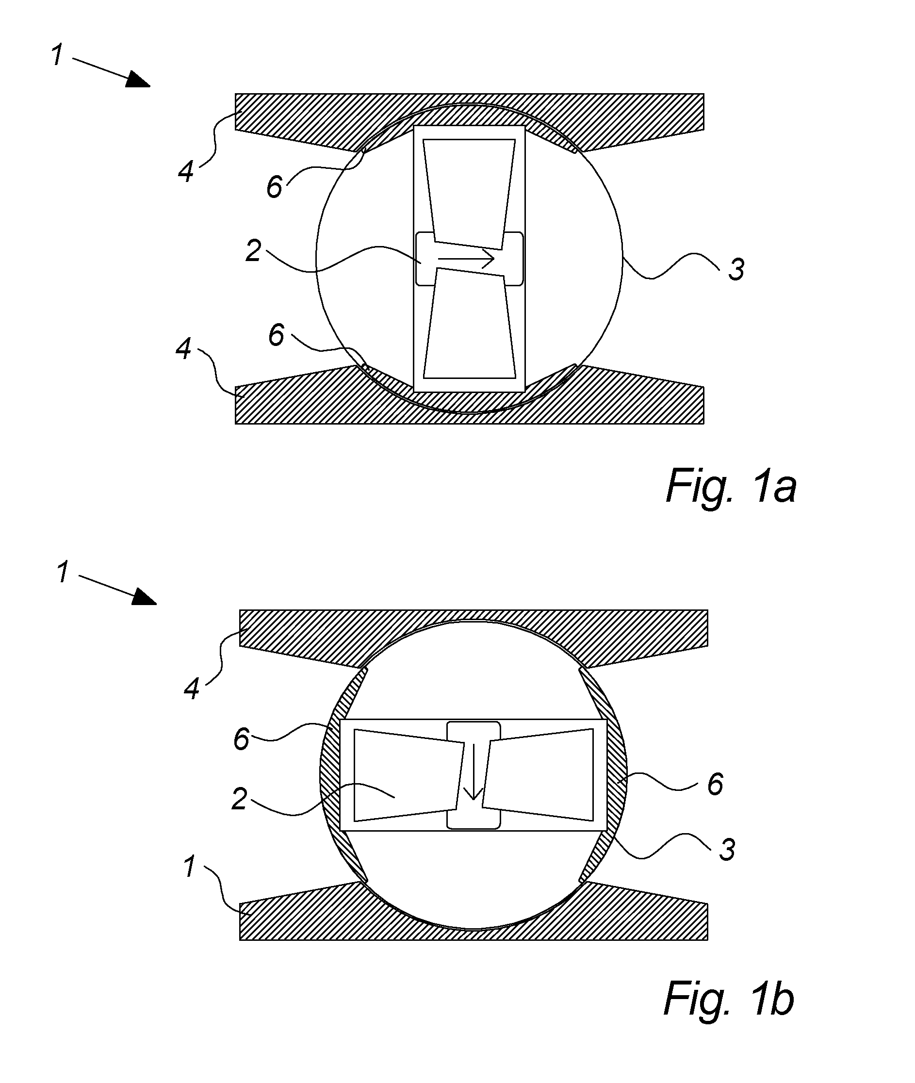
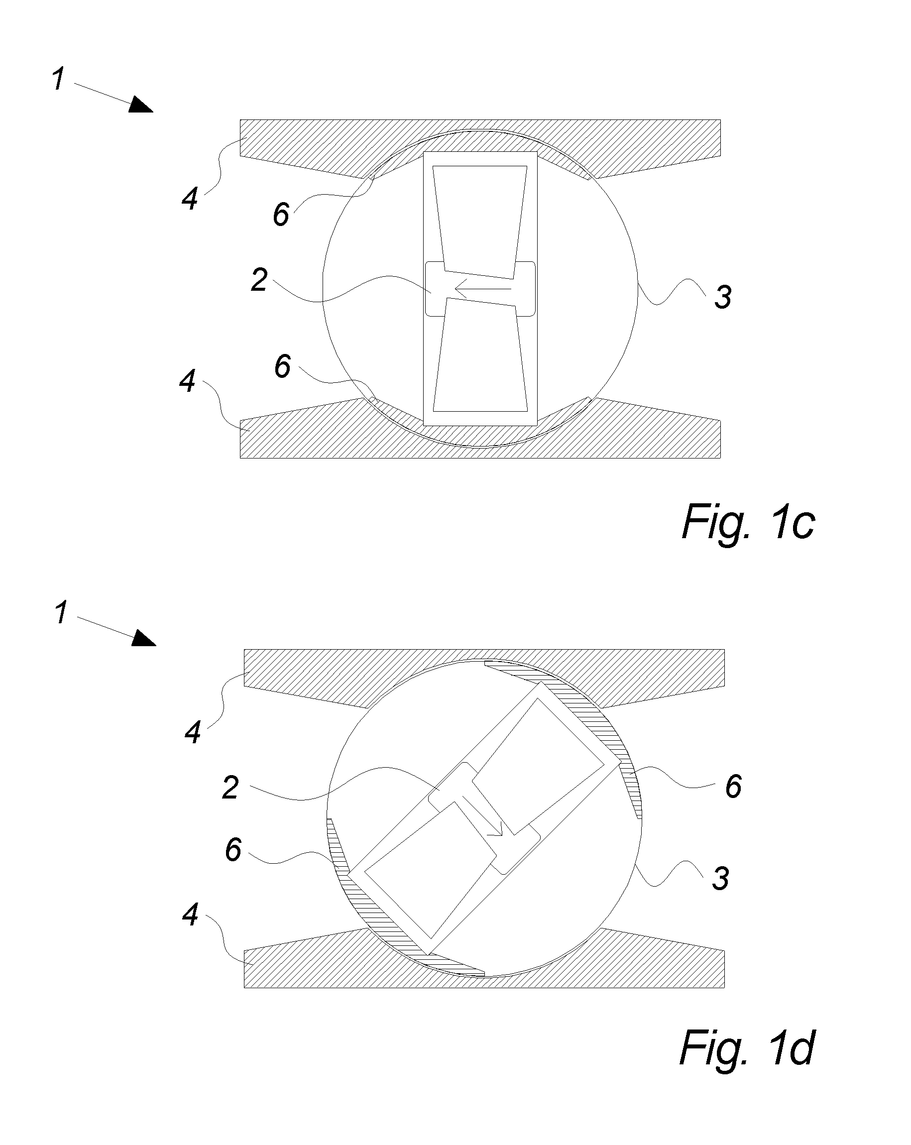
[0043]FIGS. 1a-1d schematically illustrate four different rotational positions of an air flow generator 2 of a ventilation system 1 according to an embodiment of the invention.

[0044]The air flow generator 2 is arranged in an aperture extending radially through a rotatable cylinder 3, which is mounted in a mounting frame 4 arranged inside a continuous duct 5 (not shown in FIGS. 1a-1d). Two registers 6 are fixedly connected to the air flow generator 2 so that the registers 6 move tangentially when the cylinder 3 and thereby also the air flow generator 2 is rotated about the longitudinal axis of the cylinder 3.

[0045]The small arrow in the air flow generator 2 indicates the direction of the air flow generated by the air flow generator 2 when it is active, i.e. when it is running and generating an air flow.

[0046]In a first rotational position of the air flow generator 2 as illustrated in FIG. 1a, the air flow generator 2 is positioned to generate a substantially axial air flow through th...


PUM


Abstract

A ventilation system (1) for air ventilation is disclosed, comprising a continuous duct (5) having openings at both ends, an air flow generator (2) arranged inside the duct to be rotatable around an axis of rotation so that, positioned in different rotational positions, the air flow generator is capable of producing a substantially axial air flow in each of the two directions through the duct, respectively, one or more registers arranged to be moveable between different positions, in at least one of which positions the one or more registers (6) leave the duct (5) open for air passage, whereas in another of the positions the one or more registers (6) substantially block the air passage through the duct (5), means for rotating the air flow generator (2), and means for moving the one or more registers. Furthermore, methods for controlled active and passive ventilation, respectively, through the duct of such a ventilation system (1) are disclosed.

Description

FIELD OF THE INVENTION[0001]The present invention relates to a ventilation system for air ventilation.BACKGROUND OF THE INVENTION[0002]Some ventilation systems, such as heat recovery systems in which heat energy is extracted from an air flow leaving an enclosure, such as a building, stored and added to another air flow entering the enclosure at a later point of time, require that appropriate air flows can be generated in two opposite directions.[0003]The typical solution to this problem is to provide the ventilation system with two or more air flow generators, which are oppositely oriented so that one or more air flow generators are used for generating air flows in one direction and one or more other air flow generators are used for generating air flows in the opposite direction.[0004]Some solutions trying to save space and reduce costs include the use of a system of registers, which can be placed in different positions for directing the air flow through the ventilation system in on...

Claims


Application Information

Patent Timeline
Patent Type & Authority Patents(United States)
IPC IPC(8): F24F7/06F24F12/00F24F7/00F24F13/14
CPCF24F7/065F24F13/14F24F2007/005F24F2012/008Y02B30/563F24F2013/205Y02B30/56
Inventor JENSEN, JOHN BORSTING
Owner INVENTILATE APS
Why Eureka
Try Eureka