Eyelash holder

a technology for eyelash holders and eyelashes, which is applied in the field of eyelash holders, can solve problems such as the difficulty of releasing eyelashes from such eyelash mounts

Inactive Publication Date: 2016-11-29
PRO IRODA INDS
View PDF17 Cites 44 Cited by
  • Summary
  • Abstract
  • Description
  • Claims
  • Application Information

AI Technical Summary

Benefits of technology

[0013]It is another objective of the present invention to provide an eyelash holder so that eyelashes are able to connect thereto and disconnect therefrom easily and conveniently.
[0014]It is yet another objective of the present invention to provide an eyelash holder that prevents eyelashes being disconnected therefrom from suffering deformation and breakage.

Problems solved by technology

However, it is difficult to release the eyelash from such eyelash mount.

Method used


Image

  • Eyelash holder
  • Eyelash holder
  • Eyelash holder

Examples


Embodiment Construction

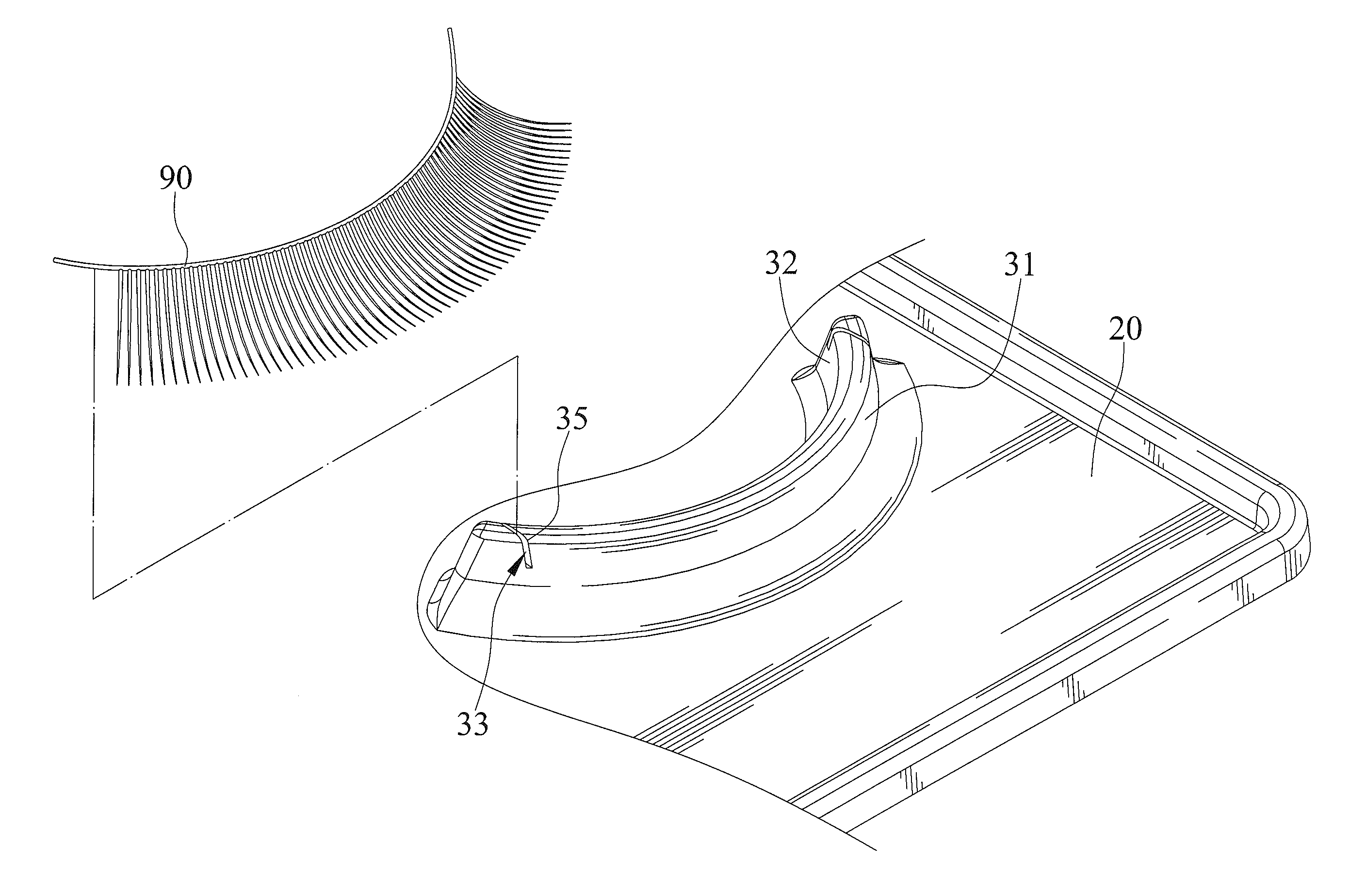
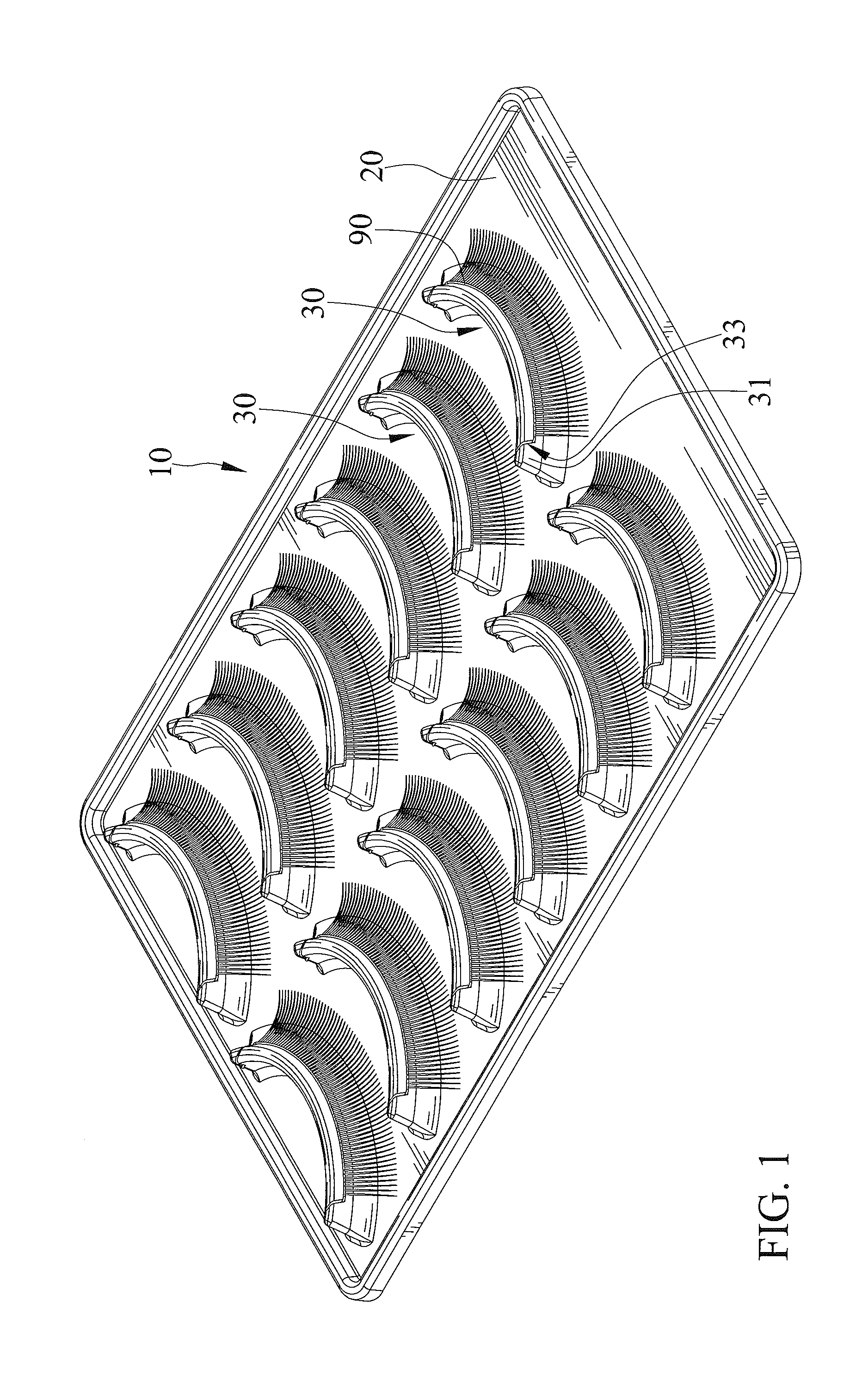
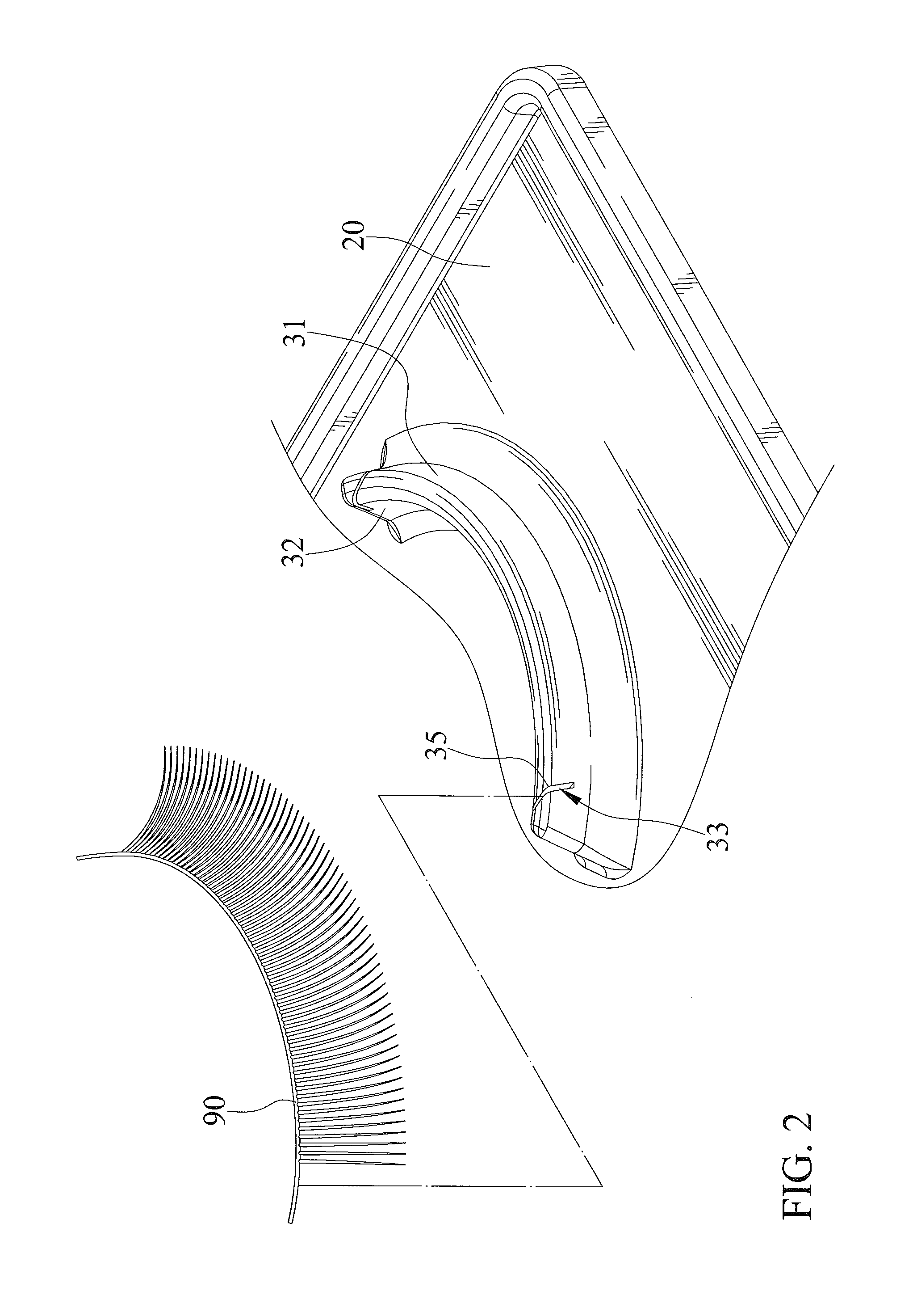
[0021]FIGS. 1 through 5 show an eyelash holder 10 in accordance with the present invention. The eyelash holder 10 includes a base 20 and at least one eyelash mount 30.

[0022]The base 20 bears and supports at least one eyelash mount 30. The at least one eyelash mount 30 is disposed on a side of the base 20. The side of the base 20 forms a flat surface. The at least one eyelash mount 30 protrudes above the side of the base 20. In the embodiment, the at least one eyelash mount 30 includes a plurality of eyelash mounts 30. In the embodiment, the plurality of eyelash mounts 30 is arranged in two columns, but is not limited thereto.

[0023]The at least one eyelash mount 30 has a top edge, a bottom edge, and two curved lateral sides. The two curved lateral sides are opposite from one another. The at least one eyelash mount 30 includes the top edge thereof extending to a top of one of the two curved lateral sides to a top of the other of the two curved lateral sides. The at least one eyelash m...


PUM

PropertyMeasurementUnit
shapeaaaaaaaaaa
heightaaaaaaaaaa
distal lengthsaaaaaaaaaa

Abstract

An eyelash holder includes a base and at least one eyelash mount supported on the base. The eyelash holder has a curved lateral side defining an eyelash positioning edge, and includes two holding slots being distal from one another and extending into the eyelash positioning edge.

Description

BACKGROUND OF THE INVENTION[0001]1. Field of the Invention[0002]The present invention relates to an eyelash holder and, particularly, to an eyelash holder allowing an eyelash to connect thereto and disconnect therefrom conveniently.[0003]2. Description of the Related Art[0004]TW Patent No. 401345 shows an eyelash holder including at least one eyelash and a base bearing the at least one eyelash. The eyelash holder can hold an eyelash with the at least one eyelash mount. The at least one eyelash mount is of a crescent shape. Therefore, an eyelash, which is normally of a crescent shape can conformingly connect to the at least one eyelash mount. In addition, an eyelash has two distal ends thereof adhering to the eyelash mount in order to be fixedly held and to avoid deformation. However, it is difficult to release the eyelash from such eyelash mount. A user would have to use a tool to break adhesive connections between the eyelash mount and the eyelash connected thereto, and to cut off ...

Claims


Application Information

Patent Timeline
Patent Type & Authority Patents(United States)
IPC IPC(8): B65D71/00A41G5/02B65D73/00B65D25/10B65D1/36
CPCA41G5/02B65D25/10B65D25/108B65D73/00B65D1/36
Inventor LIN, YU-CHIH
Owner PRO IRODA INDS
Why Eureka
Try Eureka