Color filter substrate, method for manufacturing color filter substrate, liquid crystal display device, electro-optical device, method for manufacturing electro-optical device, and electronic apparatus

Inactive Publication Date: 2005-03-22
SEIKO EPSON CORP
View PDF15 Cites 58 Cited by
  • Summary
  • Abstract
  • Description
  • Claims
  • Application Information

AI Technical Summary

Benefits of technology

According to the constructions described above, by incorporating operational effect of the liquid crystal display device or the electro-opti

Problems solved by technology

Therefore, the delimiting member 5 and the liquid material of the protective layer 4 applied thereon repel each other,

Method used


Image

  • Color filter substrate, method for manufacturing color filter substrate, liquid crystal display device, electro-optical device, method for manufacturing electro-optical device, and electronic apparatus
  • Color filter substrate, method for manufacturing color filter substrate, liquid crystal display device, electro-optical device, method for manufacturing electro-optical device, and electronic apparatus
  • Color filter substrate, method for manufacturing color filter substrate, liquid crystal display device, electro-optical device, method for manufacturing electro-optical device, and electronic apparatus

Examples


Embodiment Construction

The embodiments of color filter substrates, methods for manufacturing the same, and liquid crystal display devices in accordance with the present invention will be described below in detail with reference to the drawings.

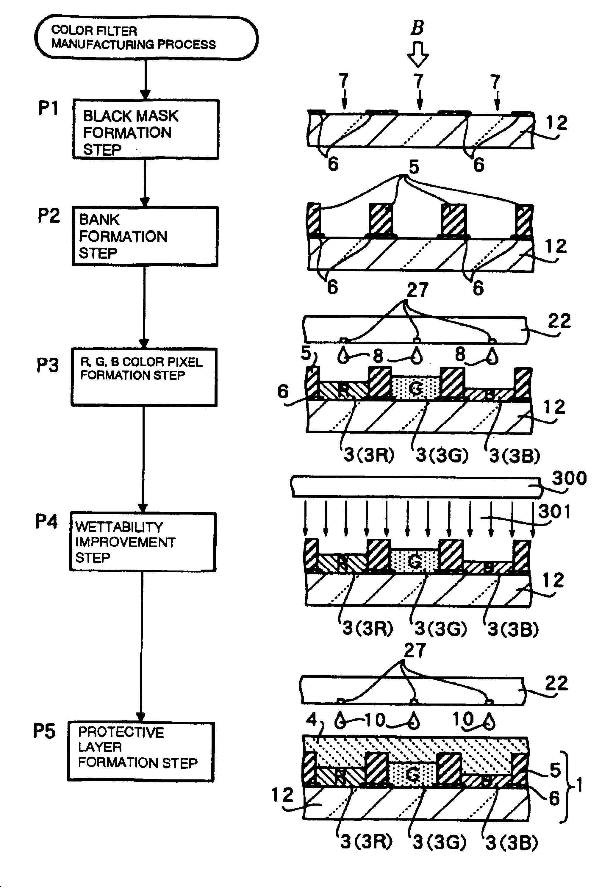
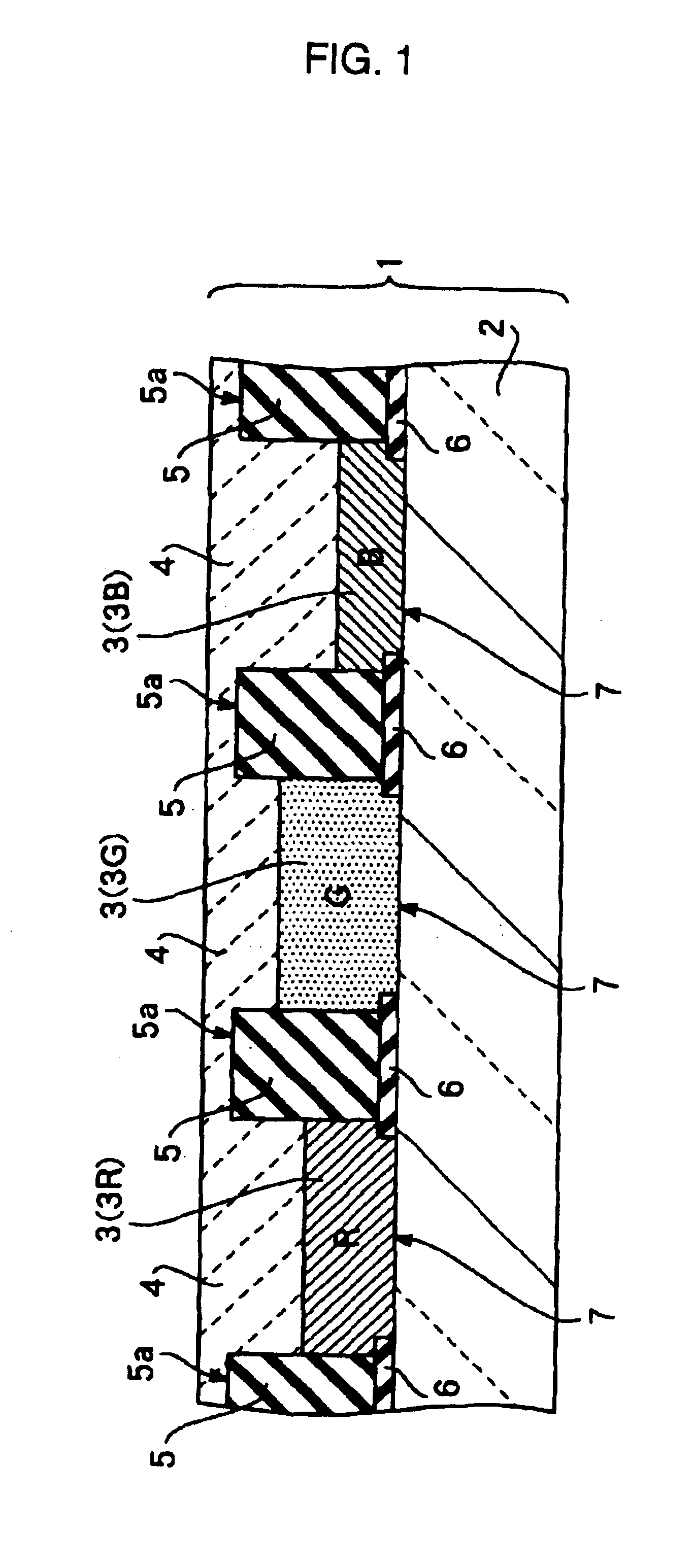
FIG. 1 is a sectional view showing the structure of a color filter substrate in an embodiment of the present invention. As shown in FIG. 1, a color filter substrate 1 includes a base member 2, a bank-like delimiting member 5 formed on the base member 2, color pixels 3, and a protective layer 4.

The delimiting member 5 is formed at a predetermined height on the base member 2 so as to delimit color-pixel-forming regions 7 having a predetermined pattern on the surface of the base member 2. The color pixels 3 are formed in the color-pixel-forming regions 7 by arranging liquid color pixel materials. The protective layer 4 is formed on the surfaces of the color pixels 3 by arranging a liquid protective layer material.

The delimiting member 5 is composed of a resin having re...


PUM


Abstract

The present invention provides a color filer substrate in which color pixels of a plurality of colors are formed in the predetermined regions delimited by a bank-like delimiting member on the surface of a base member, and protective layer is formed on the color pixels, the surface of the protective layer is modified so as to have excellent flatness. The color filter substrate can include a bank-like delimiting member having a predetermined height formed on a base member so as to delimit color-pixel-forming regions on a surface of the base member, color pixels formed in the color-pixel-forming regions by arranging liquid color pixel materials, and a protective layer formed on the surfaces of the color pixels by arranging a liquid protective layer material. The delimiting member can be composed of a resin having repellency to the color pixel material and the protective layer material. The surface of the delimiting member can be subjected to surface treatment to decrease the repellency to the liquid material constituting the protective layer.

Description

BACKGROUND OF THE INVENTION1. Field of InventionThe present invention relates to color filter substrates suitable for use in liquid crystal display devices for electronic apparatuses, such as mobile phones and mobile personal computers. The present invention also relates to methods for manufacturing such color filter substrates. The present invention also relates to liquid crystal display devices and electro-optical devices including the color filter substrates and to methods for manufacturing the electro-optical devices.More particularly, the present invention relates to a color filter substrate, in which a plurality of color pixels, such as R (red), G (green), and B (blue) pixels, or C (cyan), M (magenta), and Y (yellow) pixels, are formed in a predetermined region on a base member delimited by a bank-like delimiting member, and a protective layer is formed on the surfaces of the color pixels, to a method for manufacturing the color filter substrate, to a liquid crystal display de...

Claims


Application Information

Patent Timeline
IPC IPC(8): B41J2/14G02B5/20G02F1/1335G02F1/13B41J2/01G09F9/30
CPCB41J2/14233G02B5/201B41J2202/09G02F2001/133519B41J2202/20G02F1/133519G02F1/1335
Inventor KAWASE, TOMOMIARUGA, HISASHIKATAGAMI, SATORUITO, TATSUYA
Owner SEIKO EPSON CORP
Why Eureka
Try Eureka