
Image blur correction device, imaging lens unit, and camera unit

a technology of image blur correction and imaging lens, which is applied in the direction of camera focusing arrangement, printers, instruments, etc., can solve the problems of difficult drive control for positioning the lens within the plane vertical to the optical axis, increase the size of the first drive device, and so as to avoid disconnection, reduce the thickness and size of the device, and accurately correct the effect of image blur

Inactive Publication Date: 2011-07-28
COPAL CO LTD
View PDF6 Cites 56 Cited by
  • Summary
  • Abstract
  • Description
  • Claims
  • Application Information

AI Technical Summary

Benefits of technology

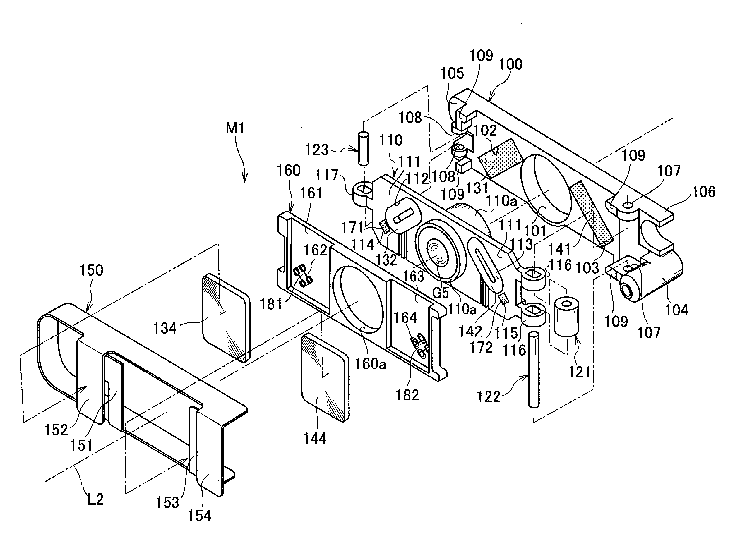
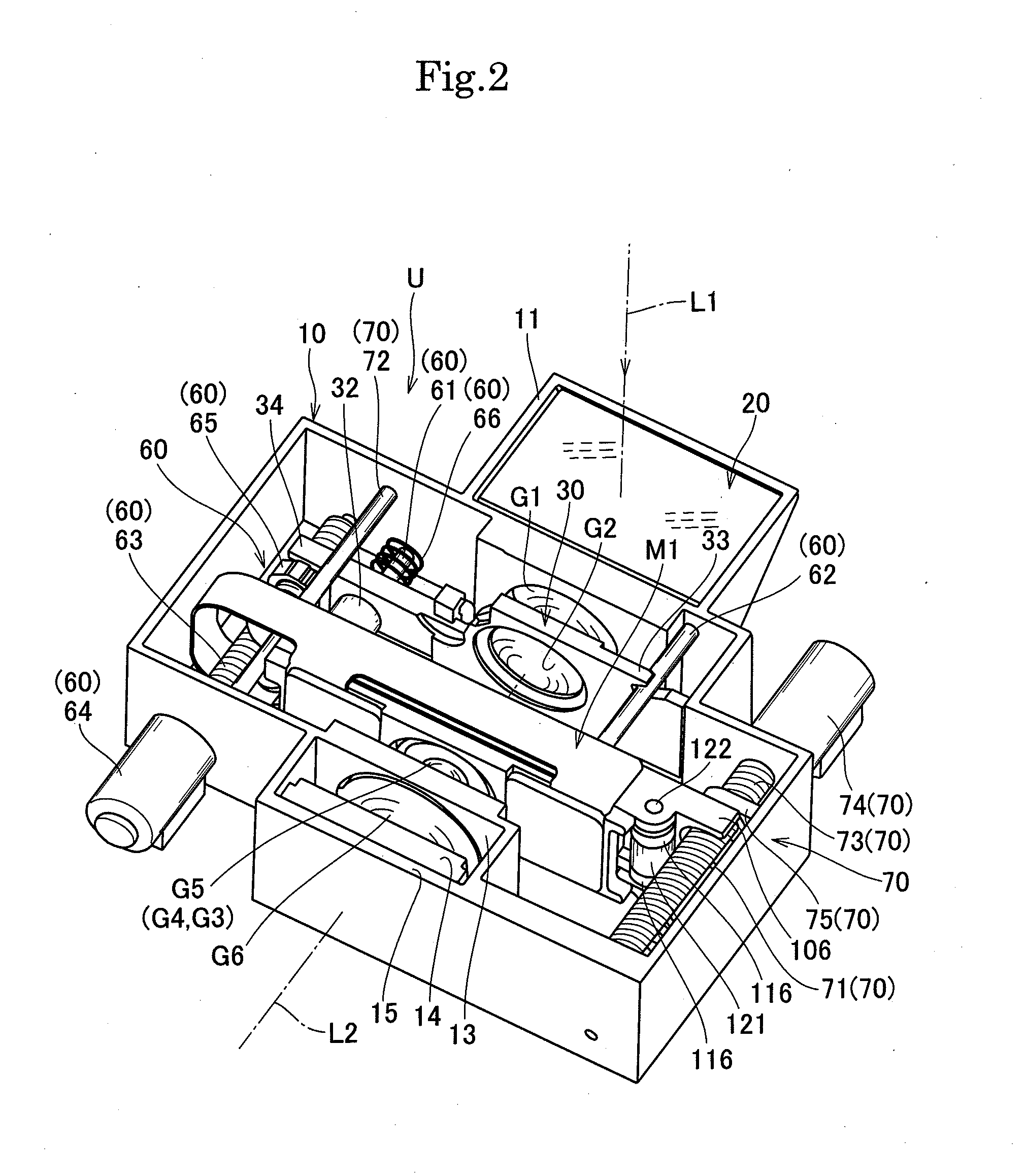
[0066]According to the image blur correction device having the above configuration, it is possible to obtain the image blur correction device that can be mounted in the camera unit of, e.g., a mobile phone while achieving a reduction in thickness and in size of the device in the optical axis direction of the lens and the direction vertical to the optical axis, highly accurately correcting an image blur caused due to hand movement and the like, avoiding disconnection and others of the electrical connection wiring lines, and automatically returning (centering) the correction lens to the predetermined pause position in the pause state, and also possible to obtain the imaging lens unit and the camera unit including this image blur correction device.

Problems solved by technology

However, this device adopts a double configuration that the first movable member and the second movable member are aligned in an optical axis direction, thus leading to an increase in size of the device in the optical axis direction.
Further, although the second drive device drives the second movable member alone, the first drive device must drive not only the first movable member but also the second movable member and the second guide shaft at the same time, larger drive force must be generated as compared with a situation where the first movable member alone is driven, thereby resulting in an increase in size of the first drive device.
Furthermore, since a drive load of the first drive device is different from a drive load of the second drive device, drive control for positioning the lens within a plane vertical to the optical axis is not easy.
Additionally, although the base is coupled with the movable member, since the fixed frame holding the coils is not integrally coupled, the image blur correction device cannot be configured as a module, its handling is inconvenient, the first magnet and the second magnet of the movable member and the first coil and the second coil of the fixed frame cannot be positioned, respectively, with one member (e.g., the base) being determined as a reference, and assembling the device is troublesome.
Therefore, a dimension of the movable body (the movable member having the coil and the detection magnet) increases in the optical axis direction, a thickness of the device in the optical axis direction increases, and reducing size and thickness of the device is difficult.
It is to be noted that, when the detection magnet is arranged around the coil to suppress the increase in thickness in the optical axis direction, a diameter of the device in the direction vertical to the optical axis increases, and reducing the size of the device is likewise difficult.

Method used


Image

  • Image blur correction device, imaging lens unit, and camera unit
  • Image blur correction device, imaging lens unit, and camera unit
  • Image blur correction device, imaging lens unit, and camera unit

Examples


second embodiment

[0451]FIG. 19 to FIG. 33 show an image blur correction device M2 according to the present invention. As shown in FIG. 19, FIG. 20, and FIG. 22, this image blur correction device M2 is incorporated in the same camera unit U as that described above, and it includes such a control unit 90 as depicted in FIG. 20.

[0452]As shown in FIG. 20 and FIG. 23 to FIG. 25, this image blur correction device M2 includes a fixed frame 200 and a cover frame 210 as a base, a movable holding member 220, a first drive mechanism 230 (including a first drive magnet 231, a first'coil 232, and first yokes 233 and 234) as a driving means, a second drive mechanism 240 (including a second drive magnet 241, a second coil 242, and second yokes 243 and 244) as a driving means, a flexible wiring board 250, a first return magnet 261 and a second return magnet 262 as a return means (return member), a first magnetic sensor 271 and a second magnetic sensor 272 as a position detecting means, and others.

[0453]As shown in ...

third embodiment

[0514]FIG. 34 to FIG. 48 show an image blur correction device M3 according to a As shown in FIG. 34 to FIG. 36, this image blur correction device M3 is incorporated in the same camera unit U as that described above, and it includes such a control unit 90 as depicted in FIG. 21.

[0515]As shown in FIG. 34 and FIG. 37 to FIG. 39, the image blur correction device M3 according to this embodiment includes a base 300, a movable holding member 310, a first drive mechanism 320 (including a first coil 321 and a first drive magnet 322) as a driving means, a second drive mechanism 330 (including a second coil 331 and a second drive magnet 332) as a driving means, yokes 341 and 342 included in the driving means, three spheres 350 as a support mechanism that movably supports the movable holding member 310 within a plane vertical to an optical axis L2, first return magnets 361 and second return magnets 362 as a return means (return members), a first magnetic sensor 371 and a second magnetic sensor...

fourth embodiment

[0576]FIG. 49 to FIG. 62 show an image blur correction device M4 according to a As shown in FIG. 49 and FIG. 50, this image blur correction device M4 is incorporated in the same camera unit U as that described above, and it includes the same control unit as that described above.

[0577]As shown in FIG. 49 to FIG. 54, the image blur correction device M4 according to this embodiment is arranged between a first movable lens group 30 and a lens G6 in an optical axis L2 direction and includes a base 400, a movable holding member 410, a first drive mechanism 420 (including a first coil 421, a first drive magnet 422, and a first yoke 423) as a driving means, a second drive mechanism 430 (including a second coil 431, a second drive magnet 432, and a second yoke 433) as a driving means, three spheres 440 as a support mechanism that movably supports the movable holding member 410 within a plane vertical to the optical axis L2, a first return magnet 451 and a second return magnet 452 as a retur...


PUM


Abstract

An image blur correction device according to the present invention includes an a base (100), a movable holding member (120), a support mechanism configured to movably support the movable holding member within a plane vertical to an optical axis of the lens, a driving means for driving the movable holding member within the plane, a position detecting means, and a return means for returning the movable holding member to a pause position in a pause state, the driving means includes a drive magnet (131, 141) fixed to one of the base and the movable holding member and a coil (132, 142) fixed to the other of the base and the movable holding member at a position where the coil faces the drive magnet, and the return means includes a return member (171, 172) consisting of a magnetic material or a magnet fixed to the other of the base and the movable holding member so as to face the drive magnet to form a magnetic force flow for returning to the pause position. As a result, simplification of the structure and a reduction in size and thickness of the device can be achieved, and a lens for correction can be automatically centered.

Description

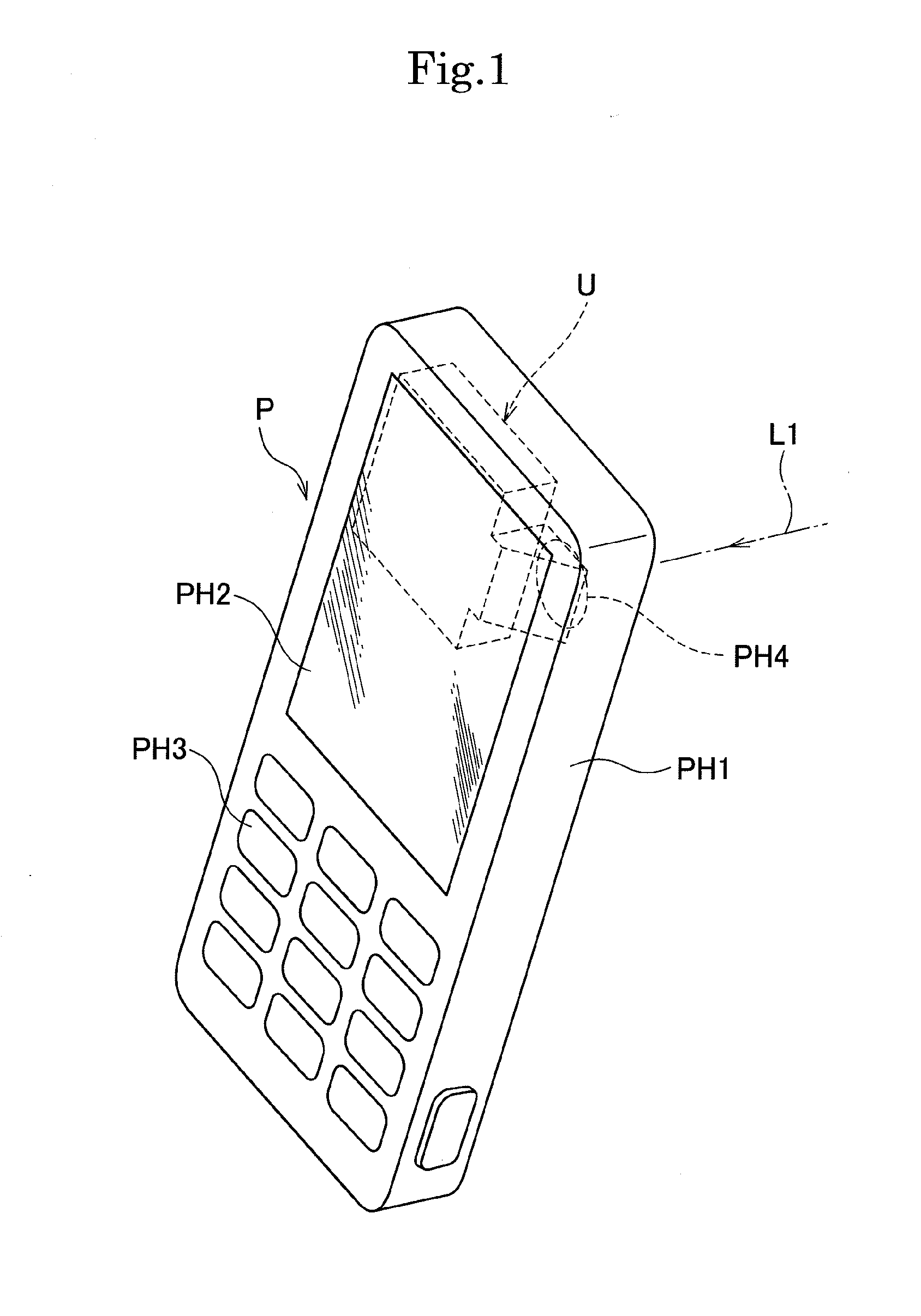
TECHNICAL FIELD[0001]The present invention relates to an image blur correction device (image stabilization device) mounted in, e.g., a lens body tube or a shutter unit in a digital camera, and to an imaging lens unit and a camera unit including this image blur correction device, and more particularly to a small and thin image blur correction device applied to a camera unit mounted in a personal digital assistance such as a mobile phone, and to an imaging lens unit and a camera unit.BACKGROUND ART[0002]As a conventional image blur correction device (image stabilization device), there is known an image blur correction device including: a substantially rectangular base having an opening portion at the center; a first guide shaft provided on a front surface of the base; a first movable member supported to be reciprocable along the first guide shaft; a second guide shaft directed to a 90-degree direction with respect to the first guide shaft and provided on a front surface of the first m...

Claims


Application Information

Patent Timeline
Patent Type & Authority Applications(United States)
IPC IPC(8): H04N5/228H04N23/40
CPCG03B3/10G03B5/00G03B5/02H04N5/23287G03B13/36H04N5/23248G03B5/04H04N23/68H04N23/687
Inventor WATANABE, HIROYUKIKURABE, AGNIESZKA
Owner COPAL CO LTD
Learn More