Projector and method of correcting image distortion

a projector and image technology, applied in the field of projectors, can solve the problems of projectors are often limited to certain installations, and distortion correction circuits that cannot perform the distortion correction process properly

Active Publication Date: 2005-04-12
SHARP NEC DISPLAY SOLUTIONS LTD
View PDF10 Cites 46 Cited by
  • Summary
  • Abstract
  • Description
  • Claims
  • Application Information

AI Technical Summary

Benefits of technology

[0015]It is therefore an object of the present invention to provide a projector which is capable of correcting distortion of projected images properly regardless of different zoom settings of an optical zoom means, even when the images are

Problems solved by technology

Projectors are often limited to certain installation positions in the environments in which they are used, and project images onto a projection surface such as a screen or the like along an optical axis that is oblique to the projection surface.
Therefore, these conventional projectors are disadvantageous in that the distortion correcting circuit is unable to perform the distortion correcting process properly for the other magnification setting.
The reason why the distortion correcting process cannot be performed properly is that dist

Method used


Image

  • Projector and method of correcting image distortion
  • Projector and method of correcting image distortion
  • Projector and method of correcting image distortion

Examples


Embodiment Construction

process of correcting image distortion based on a zoom setting that is detected by a zoom setting detector;

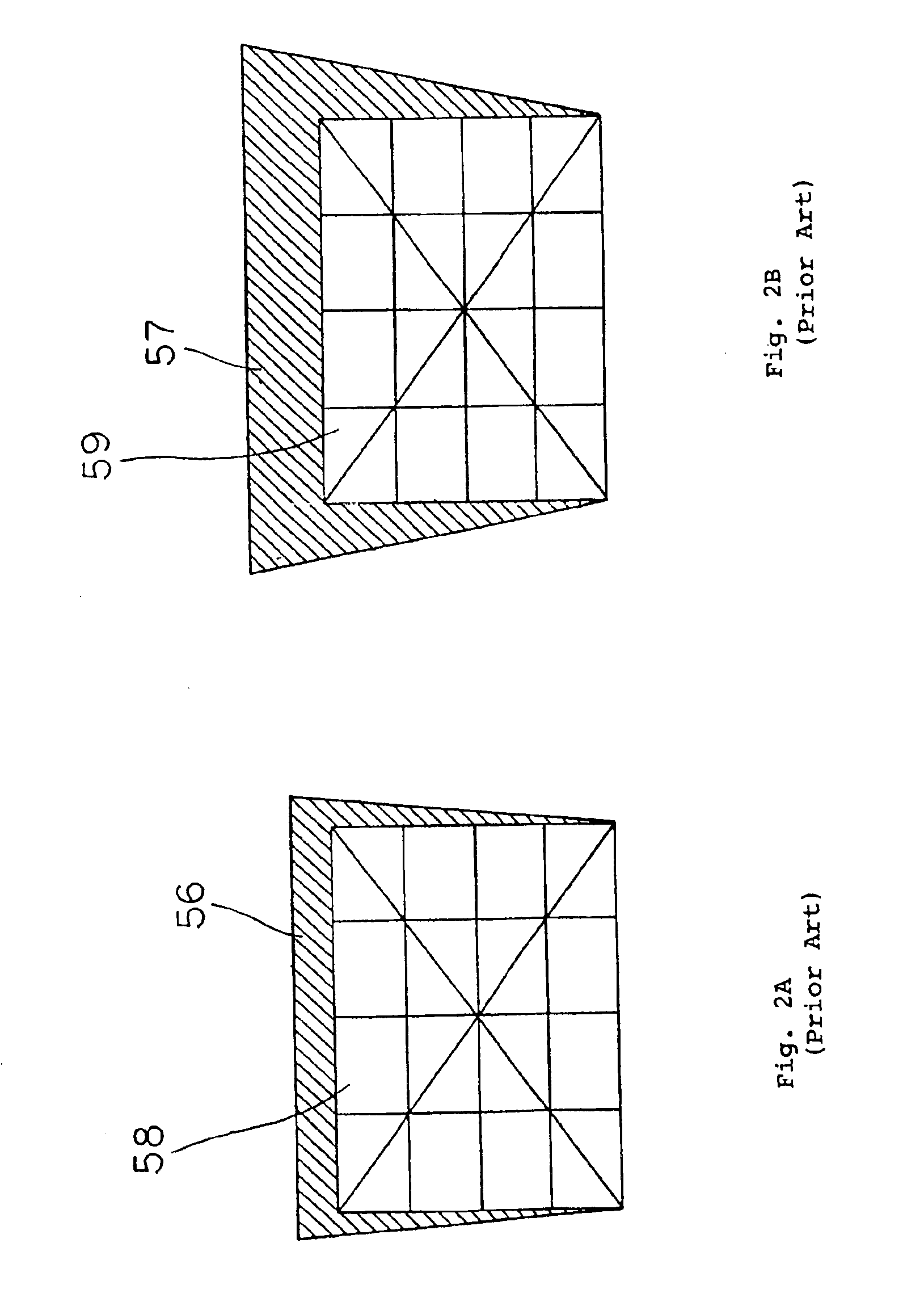
[0025]FIG. 5A is a view of a projection surface, showing the manner in which a projected image is corrected at a wide angle end setting;

[0026]FIG. 5B is a view of an image displayed on an image display unit;

[0027]FIG. 6A is a view of a projection surface, showing the manner in which a projected image is corrected at a telephoto end setting; and

[0028]FIG. 6B is a view of an image displayed on the image display unit.

DESCRIPTION OF THE PREFERRED EMBODIMENT

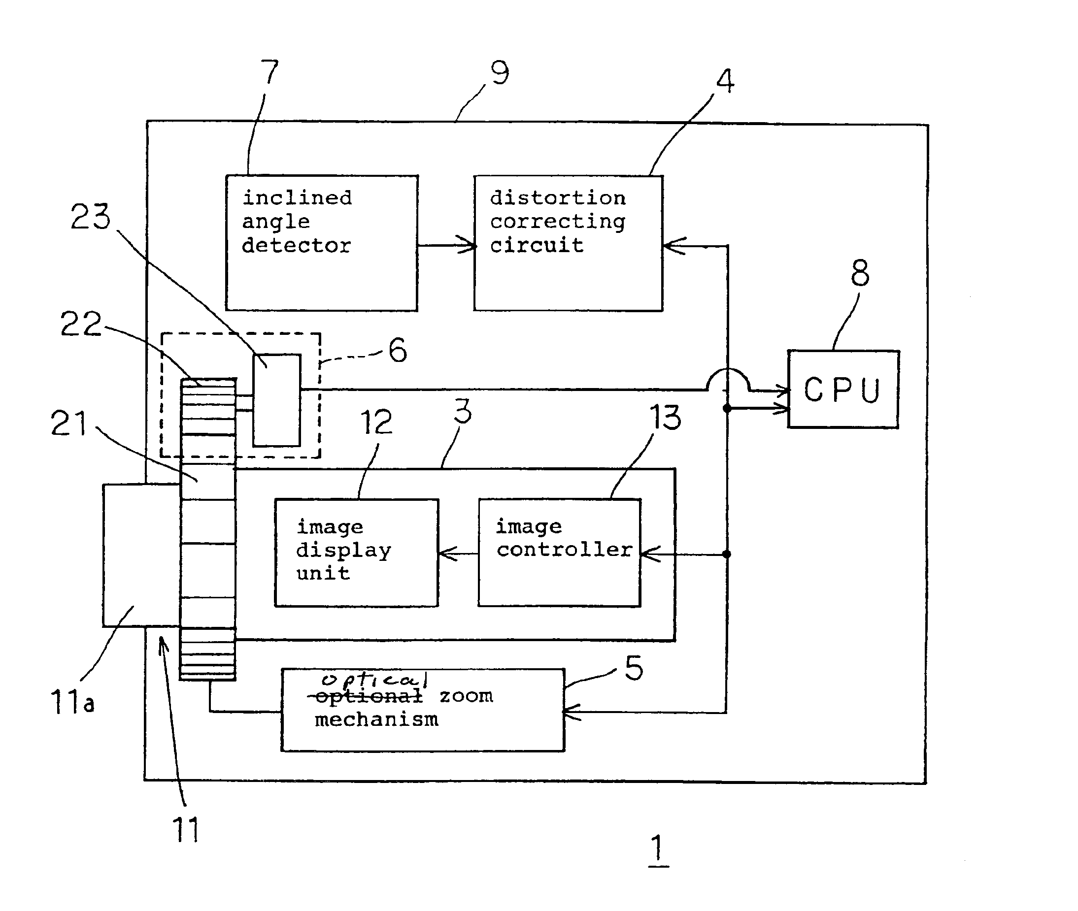
[0029]As shown in FIG. 3, projector 1 according to an embodiment of the present invention comprises projection unit 3 having projection optical system 11 for projecting images onto a projection surface such as a screen or the like, distortion correcting circuit 4 as a distortion correcting means for correcting distortion of images projected onto the projection surface, optical zoom mechanism 5 as an optical zoom means for enlargi...


PUM


Abstract

Projector has projection optical system for projecting an image onto a projection surface and optical zoom mechanism for actuating projection optical system to enlarge and reduce the image projected onto the projection surface. Projector also has distortion correcting circuit for correcting distorted quadrilateral projected images, which are projected onto the projection surface along an optical axis that is oblique vertically and horizontally to the projection surface, into respective square corrected images, zoom setting detector for detecting a zoom setting of optical zoom mechanism, and CPU for generating corrective data to be set in distortion correcting circuit based on the zoom setting detected by zoom setting detector.

Description

BACKGROUND OF THE INVENTION[0002]1. Field of the Invention[0003]The present invention relates to a projector for projecting images onto a projection surface such as a screen or the like, and more particularly to a projector for correcting distortion of images to be projected onto a projection surface and projecting distortion-corrected images onto the projection surface, and a method of correcting such distortion of images to be projected onto a projection surface.[0004]2. Description of the Related Art[0005]Projectors are often limited to certain installation positions in the environments in which they are used, and project images onto a projection surface such as a screen or the like along an optical axis that is oblique to the projection surface. In such a case, when an image having a square image area is projected onto the projection surface, the projected image suffers a trapezoidal or quadrilateral distortion. Therefore, conventional projectors have a distortion correcting cir...

Claims


Application Information

Patent Timeline
IPC IPC(8): G03B41/00G03B41/02G03B21/26G03B21/00G03B21/14G09G5/00H04N5/74G09G3/00
CPCG03B21/14H04N5/74G09G3/002G09G2320/02G03B21/142G03B21/53H04N9/3185H04N9/3194
Inventor TAMURA, YOUICHIITAKI, YOUICHI
Owner SHARP NEC DISPLAY SOLUTIONS LTD
Why Eureka
Try Eureka