Hidden type sliding rail assembly auto locking structure for drawer

a sliding rail and drawer technology, applied in the field of hidden type sliding rail assembly, can solve the problems of difficult spring replacement, inability to push the drawer to the rear side, and the auto locking structure fails to function normally, so as to prevent the disconnection of the locking block, short working life, and small size

Inactive Publication Date: 2008-05-20
GSLIDE
View PDF7 Cites 58 Cited by
  • Summary
  • Abstract
  • Description
  • Claims
  • Application Information

AI Technical Summary

Benefits of technology

[0002]FIGS. 1 and 2 illustrate a sliding rail assembly auto locking structure used in a sliding rail assembly 9 for drawer. This sliding rail assembly auto locking structure comprises a holder base 91, a spring member 92, a slide 93, and a push block 941 at the inner sliding rail 94. Because the spring member 92 is mounted in a spring chamber 912 inside the holder base 91, the spring member 92 is forced to rub against the inside wall of the spring chamber 912 when it is alternatively compressed and stretched. Therefore, the spring member 92 wears quickly with use. Further, it is difficult to replace the spring member 92 when the spring member 92 is damaged. Further, the slide 93 has two guide rods 931 and 932 for guiding reciprocating motion of the slide 93 in a sliding groove 911 inside the holder base 91. The sliding groove 911 has a downwardly extending front retaining groove portion 9111 for receiving one guide rod 931. When the user arranges the drawer or touches the drawer accidentally, the guide rod 931 of the slide 93 may be forced out of the front retaining groove portion 9111 of the sliding groove 911, causing the slide 93 to be pulled backwards by the spring member 92. In this case, the auto locking structure fails to function normally, and the drawer cannot be pushed to the rear side. U.S. Pat. Nos. 5,207,781 and 5,302,016 and PCT WO 01 / 8279A2 have same drawbacks. Further, the spring member 93 has one end hooked on one guide rod 931 of the slide 93 and is kept in a oblique manner, i.e., the spring member 93 is not horizontally stretched and compressed, resulting in instability of the reciprocating motion of the slide 93 and short working life of the spring member 93. Further, because the slide 93 vibrates heavily when it is pulled directly by the spring member 92 during its return stroke. Therefore, it is desirable to provide a sliding rail assembly auto locking structure that eliminates the aforesaid drawbacks.
[0003]The present invention has been accomplished under the circumstances in view. According to one aspect of the present invention, the hidden type sliding rail assembly auto locking structure is comprised of a holder base, a slide, a coil spring member, a hook, a steel spring strip, a locking block, and an actuating block. When the outer sliding rail is moved outwards with the drawer, the actuating block is stopped against the steel spring strip to force the hook against the slide, and at the same time the locking block is inserted into a side notch of the holder base and stopped at a stop edge at one side of the side notch to prevent disconnection of the locking block from the stop edge upon a vibration of the drawer due to an accidental condition. When the outer sliding rail is moved backwards with the drawer, the actuating block is stopped against the hook to bias the hook and to further move the locking block away from the stop edge of the holder base for allowing the steel spring strip to be forced against the actuating block of the outer sliding rail to push the outer sliding rail and the drawer backwards to the close position, thereby achieving the auto locking effect.
[0004]According to another aspect of the present invention, the slide, the hook, the spring member and the locking block are mounted in the holder base. The whole assembly has a small size that does not require much installation space. Further, the holder base does not need a cover to keep the inside parts from sight, thereby saving much installation labor and time.
[0005]According to still another aspect of the present invention, the hook does not bias outwards when the drawer is forced accidentally by an external force, and the user can directly push the drawer backwards to force the actuating block over the oblique steel spring strip to the position between the steel spring strip and the hook, and therefore the drawer is accurately returned to the close position.
[0006]According to still another aspect of the present invention, the spring member is provided outside the holder base. When the spring member is stretched or compressed, the spring member does not rub against the outside wall of the holder base. Therefore, the spring member is durable in use and replacement of the spring member can easily be performed.
[0007]According to still another aspect of the present invention, the hook is pivoted to the slide, and the slide is connected to the spring member. This arrangement assures smooth reciprocation of the slide in the holder base. Further, a hydraulic cylinder is used to buffer the return stroke of the slide, eliminating noise.BRIEF DESCRIPTION OF THE DRAWING

Problems solved by technology

Further, it is difficult to replace the spring member 92 when the spring member 92 is damaged.
In this case, the auto locking structure fails to function normally, and the drawer cannot be pushed to the rear side.
Further, the holder base does not need a cover to keep the inside parts from sight, thereby saving much installation labor and time.

Method used


Image

  • Hidden type sliding rail assembly auto locking structure for drawer
  • Hidden type sliding rail assembly auto locking structure for drawer
  • Hidden type sliding rail assembly auto locking structure for drawer

Examples


Embodiment Construction

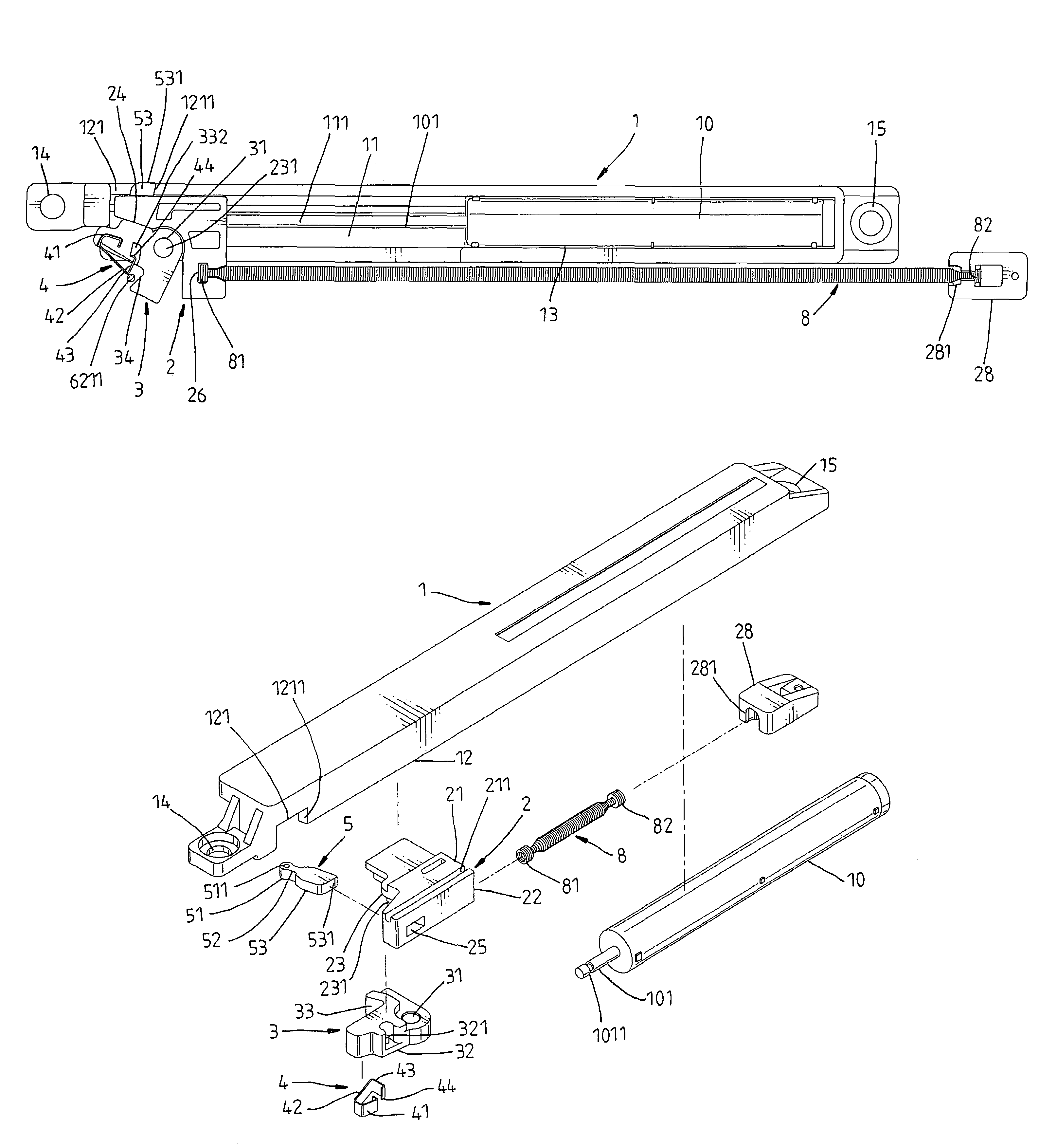
[0022]Referring to FIGS. 3˜14, a sliding rail assembly auto locking structure is shown used in a sliding rail assembly 6 for drawer (see FIG. 13). The sliding rail assembly 6 has an inner sliding rail 61 affixed to the deck, and an outer sliding rail 62 affixed to a drawer. The sliding rail assembly auto locking structure comprises a holder base 1, a slide 2, a hook 3, a steel spring strip 4, a locking block 5, a actuating block 6211, and a spring member 8.

[0023]The holder base 1 has a front mounting through hole 14 and a rear mounting through hole 15 affixed to the bottom wall 611 of the inner sliding rail 61 of the sliding rail assembly 6 with screws 16 and 17 (see FIG. 13), an inside sliding wall 11 on which the slide 2 is reciprocated (see FIG. 5), a guide wall 12 extending along one lateral side of the inside sliding wall 11 for guiding movement of the slide 2 on the inside sliding wall 11, a side notch 121 cut through one end of the guide wall 12, and a stop edge 1211 disposed...


PUM


Abstract

A hidden type sliding rail assembly auto locking structure for drawer is disclosed comprised of a holder base, a slide, a coil spring member, a hook, a steel spring strip, a locking block, and an actuating block. When the outer sliding rail is moved outwards with the drawer, the actuating block pushes the steel spring strip to force the hook against the slide and to further force the locking block into a side notch and stopped at a stop edge at the holder base to prevent disconnection of the locking block, for enabling the coil spring member to return the drawer to the close position. Except the coil spring member, the holder base holds the other parts on the inside and keeps them from sight without the use of a cover, thereby saving much installation labor and time.

Description

BACKGROUND AND SUMMARY OF THE INVENTION[0001]The present invention relates to a sliding rail assembly for drawer and more specifically, to a hidden type auto locking structure used in a sliding rail assembly for drawer, which has a small size that does not require much installation space and, which keeps the parts from sight without the use of a cover.[0002]FIGS. 1 and 2 illustrate a sliding rail assembly auto locking structure used in a sliding rail assembly 9 for drawer. This sliding rail assembly auto locking structure comprises a holder base 91, a spring member 92, a slide 93, and a push block 941 at the inner sliding rail 94. Because the spring member 92 is mounted in a spring chamber 912 inside the holder base 91, the spring member 92 is forced to rub against the inside wall of the spring chamber 912 when it is alternatively compressed and stretched. Therefore, the spring member 92 wears quickly with use. Further, it is difficult to replace the spring member 92 when the spring...

Claims


Application Information

Patent Timeline
Patent Type & Authority Patents(United States)
IPC IPC(8): A47B88/04
CPCA47B88/047A47B88/467
Inventor LU, CHUN-MIN
Owner GSLIDE
Why Eureka
Try Eureka