
Dental implant assembly for uniform distribution of occlusal forces

a technology of occlusal forces and dental implants, applied in dental implants, dental surgery, medical science, etc., can solve the problems of inadequate force distribution, dental implants fail to effectively mimic the shock absorption characteristics of periodontal ligaments (pdl), and dental implants fail to effectively mimic the force of periodontal ligaments, so as to maintain the microvascularity and viable structural support of alveolar bones, reduce deleterious forces, and dissipate vertical, horizontal and angular forces

Active Publication Date: 2016-12-20
VUKAS STEVEN
View PDF11 Cites 4 Cited by
  • Summary
  • Abstract
  • Description
  • Claims
  • Application Information

AI Technical Summary

Benefits of technology

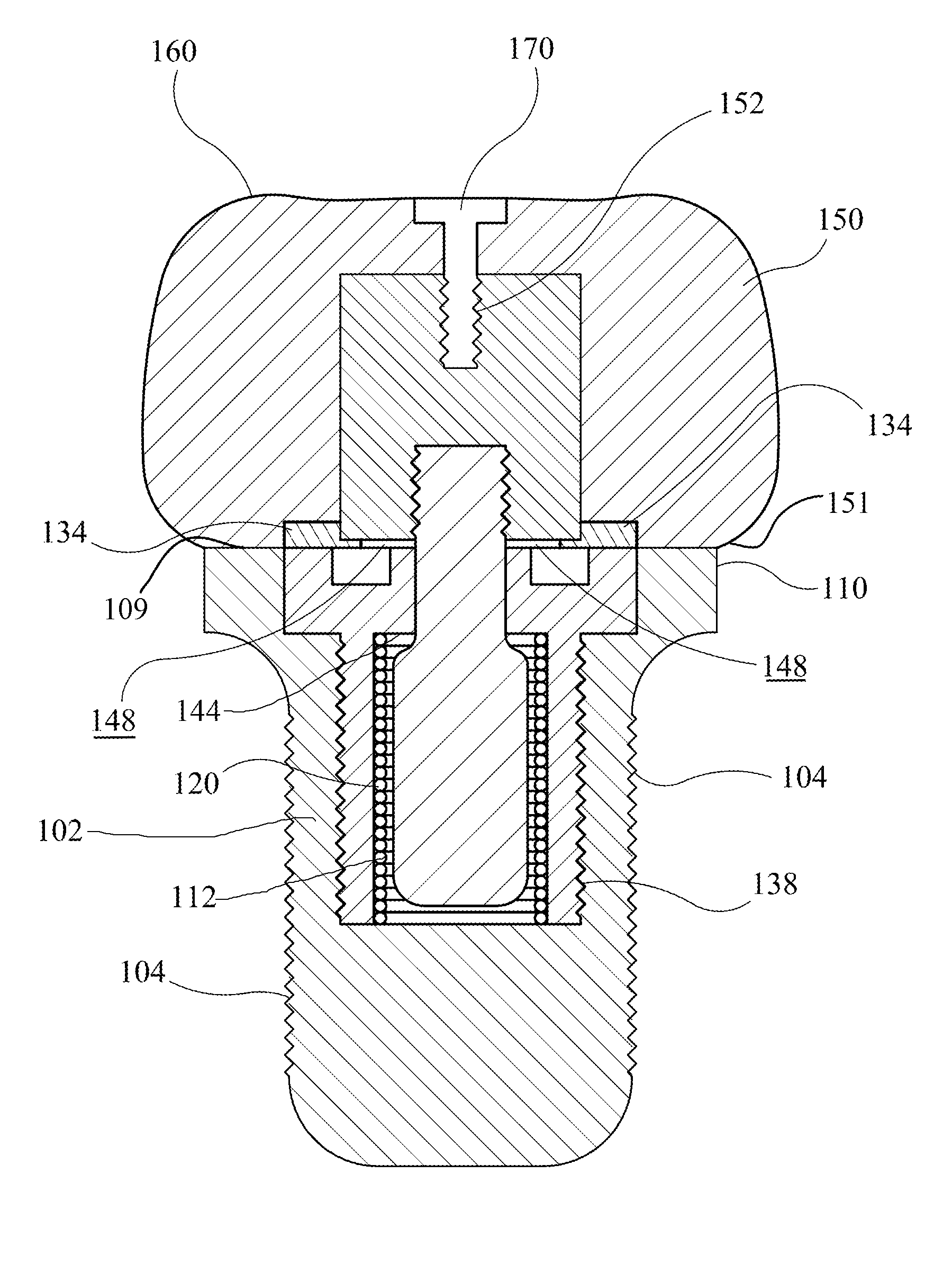
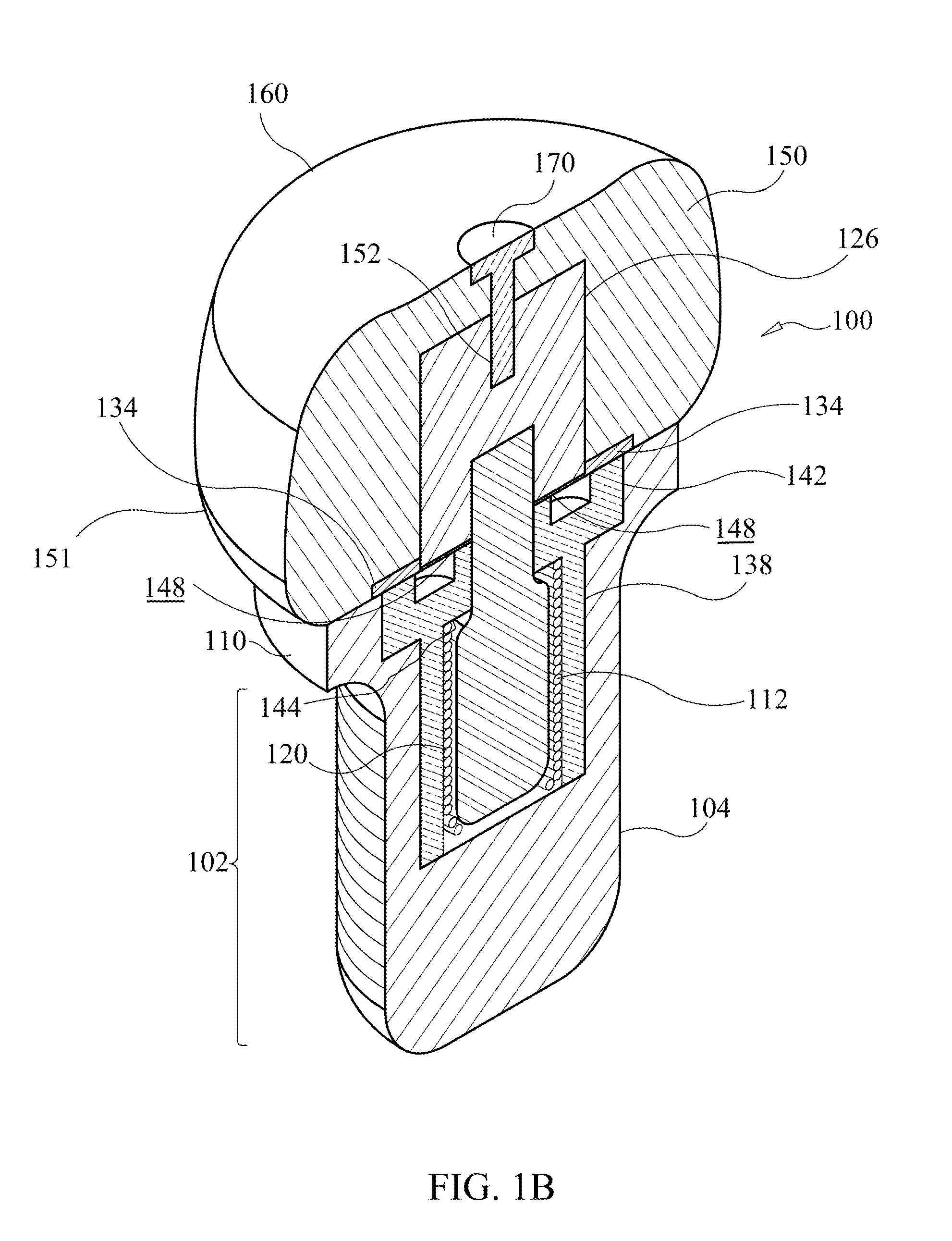
The present disclosure is about a dental implant abutment assembly that uses a special mechanism to distribute and direct external forces in a way that reduces damage to the bone. This mechanism, called micro-motion, mimics the behavior of the periodontal ligament, which helps maintain the health of the bone. The assembly compresses into the dental implant and uses a central mobile element, a compressive coil, and a compressive ring to disperse the forces and reduce the risk of damage. This design directs most of the forces to the cancellous bone, which is more vascular and flexible than the cortical bone, minimizing the risk of complications. The assembly provides uniform and safe distribution of forces, improving the longevity and function of dental implants.

Problems solved by technology

However, dental implants fail to effectively mimic the shock absorbing characteristics of the periodontal ligament (PDL) for force distribution inherent in natural teeth.
One of the major factors for dental implant failure is inadequate force distribution.
This phenomenon can occur with single or multiple unit implant restorations, leading to mechanical overload of the dental implants.
These forces, vertical, horizontal, and angular, can cause micro motion (especially compression) of the dental implant within the alveolar bone housing which can cause microvascular injury to the supporting alveolar bone, resulting in alveolar bone degeneration from avascular necrosis and recession of viable supporting alveolar bone around the dental implant potentially resulting in implant disintegration from the alveolar housing under function as alveolar bone support on the dental implant decreases.
Higher functional forces cause microvascular damage and occlusion of vascular structures resulting in decreased blood flow and subsequent loss of viability resulting in alveolar bone recession along the alveolar bone / dental implant interface.
The problem with these devices is that they do not have the benefit of compressive force dissipation inherent in a periodontal ligament.
Thus, an unaddressed need exists in the industry to address the aforementioned deficiencies and inadequacies.
Even though the above cited methods for a dental implant meets some of the needs of the market, a dental implant assembly that utilizes a central mobile element, a compressive coil and a compressive ring to direct occlusal forces internally and inferiorly to distribute the occlusal forces uniformly is still desired.

Method used


Image

  • Dental implant assembly for uniform distribution of occlusal forces
  • Dental implant assembly for uniform distribution of occlusal forces
  • Dental implant assembly for uniform distribution of occlusal forces

Examples


Embodiment Construction

[0056]The following detailed description is merely exemplary in nature and is not intended to limit the described embodiments or the application and uses of the described embodiments. As used herein, the word “exemplary” or “illustrative” means “serving as an example, instance, or illustration.” Any implementation described herein as “exemplary” or “illustrative” is not necessarily to be construed as preferred or advantageous over other implementations. All of the implementations described below are exemplary implementations provided to enable persons skilled in the art to make or use the embodiments of the disclosure and are not intended to limit the scope of the disclosure, which is defined by the claims. For purposes of description herein, the terms “upper,”“lower,”“left,”“rear,”“right,”“front,”“vertical,”“horizontal,”“cross-sectional,”“sectional” and derivatives thereof shall relate to the disclosure as oriented in FIG. 1A. Furthermore, there is no intention to be bound by any e...


PUM


Abstract

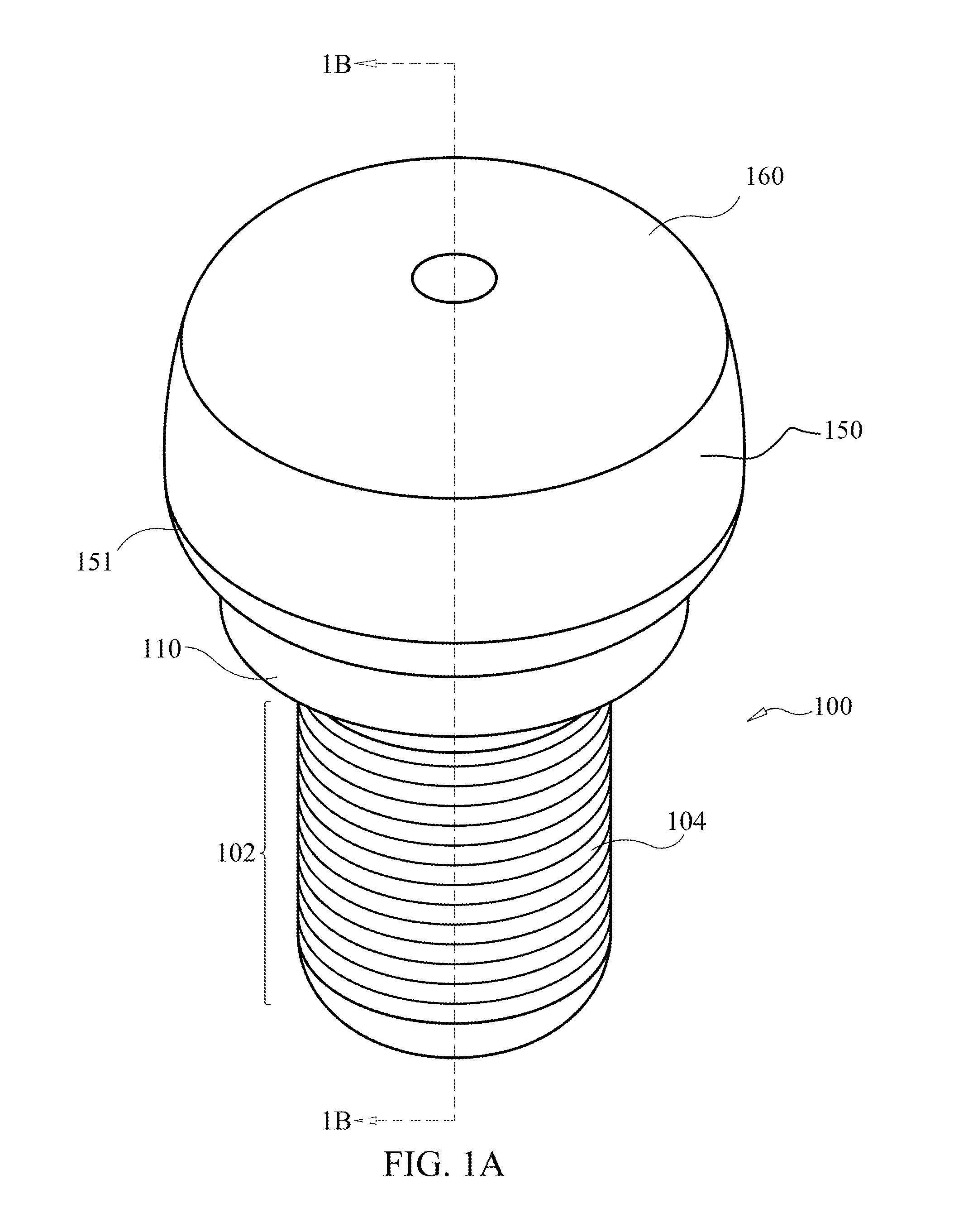
A dental implant abutment assembly imitates a micro-motion mechanism to direct occlusal forces internally, and uniformly distribute the occlusal forces into the body of an ossoeintegrated dental implant. The micro-motion mechanism is configured to imitate the biomechanical behavior of the periodontal ligament through a compressive action that dampens vertical, horizontal, and angular forces. A compressive ring provides a dampening effect to supportive components of the assembly. A compressive coil redirects vertical forces along a longitudinal axis of the assembly. An implant body osseointegrates into the dental alveolus. A central mobile element seats in the dental body. The compressive coil extends along the central mobile element to absorb vertical forces. The compressive ring seats on the collar of the dental implant. A threaded cannulated housing securely holds the central mobile element and the compressive coil to form a single unit. A restorative abutment portion threadably seats on the central mobile element.

Description

FIELD OF THE DISCLOSURE[0001]The present disclosure relates generally to a dental implant abutment assembly that uniformly distributes occlusal forces during function. More so, a dental implant abutment assembly with an integrated micro-motion mechanism comprising a central mobile element, compressive coil and a compressive ring uniformly distributing occlusal forces into the body of an osseointegrated dental implant. This dental implant assembly effectively directs a greater concentration of functional forces into the body of the dental implant which resides in the cancellous alveolar bone which has more vascularity and greater pliability under function than the crestal cortical alveolar bone, where most occlusal forces on dental implants are usually concentrated. Thus, the cancellous alveolar bone, because of the aforementioned characteristics, is less prone to untoward complications from microvascular compressional bone necrosis than the cortical alveolar bone, providing a better...

Claims


Application Information

Patent Timeline
Patent Type & Authority Patents(United States)
IPC IPC(8): A61C8/00
CPCA61C8/0086A61C8/0012A61C8/0022A61C8/0054A61C8/0068A61C8/0074A61C8/0089A61C8/005
Inventor VUKAS, STEVEN
Owner VUKAS STEVEN
Learn More