Power generating element

a technology of power generating element and magnetostrictive rod, which is applied in the direction of piezoelectric/electrostrictive/magnetostrictive devices, piezoelectric/electrostrictive/magnetostriction machines, etc., can solve the problem of hard to say that the power generating unit described in the patent document 1 has sufficient connecting forces between these components, and achieves the effect of improving power generating efficiency, reliability of magnetostrictive rods,

Active Publication Date: 2016-12-20
MITSUMI ELECTRIC CO LTD
View PDF16 Cites 0 Cited by
  • Summary
  • Abstract
  • Description
  • Claims
  • Application Information

AI Technical Summary

Benefits of technology

[0034]According to the present invention, it is possible to reliably fix the magnetostrictive rod to the other components, and thereby efficiently carrying out the expansion and the contraction of the magnetostrictive rod. As a result, it is possible to improve power generating efficiency.

Problems solved by technology

However, it is hard to say that the power generating unit described in the patent document 1 has sufficient connecting forces between these components.

Method used


Image

  • Power generating element
  • Power generating element
  • Power generating element

Examples


first embodiment

[0042]First, description will be given to a power generating element according to a first embodiment of the present invention.

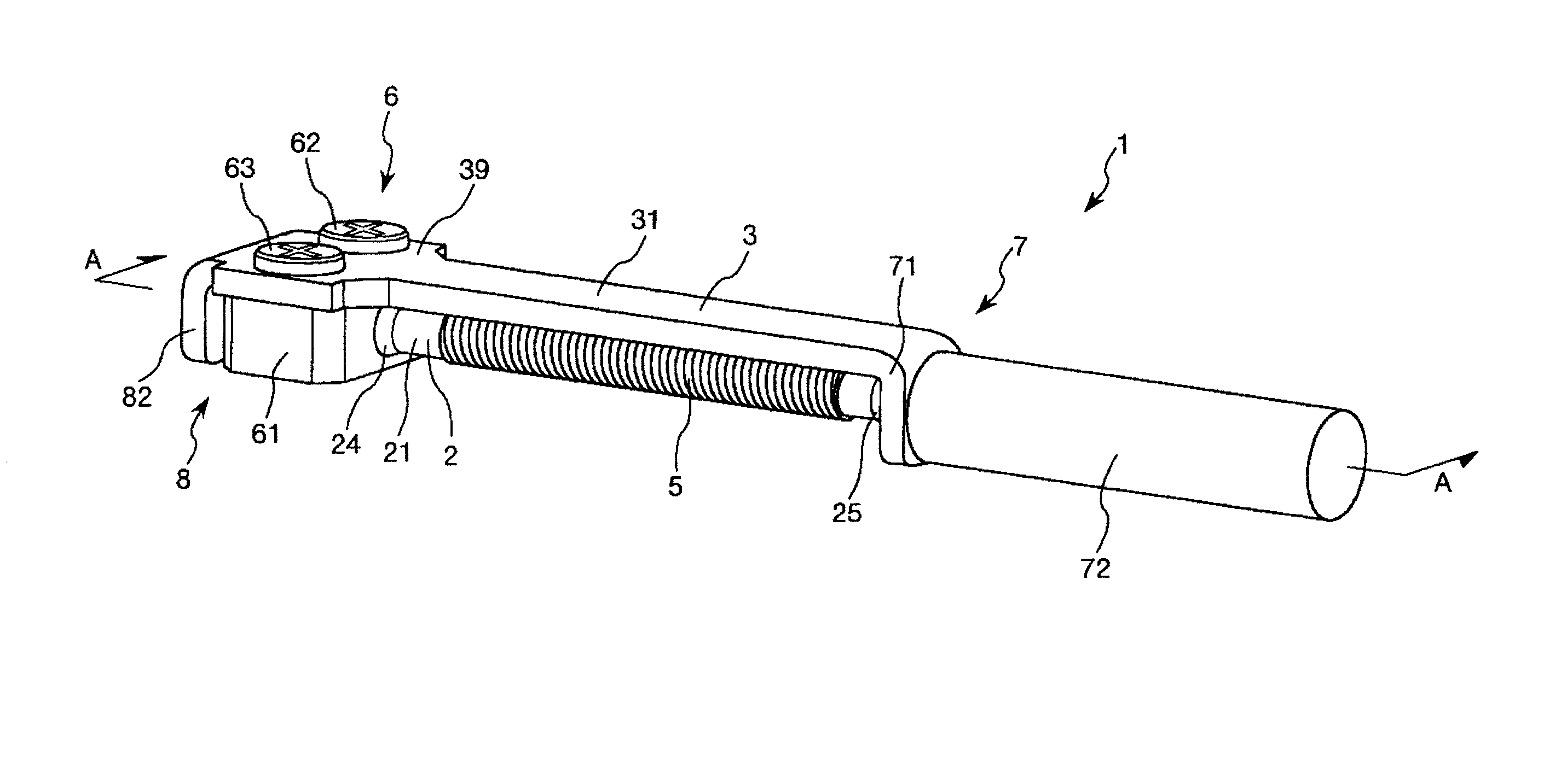
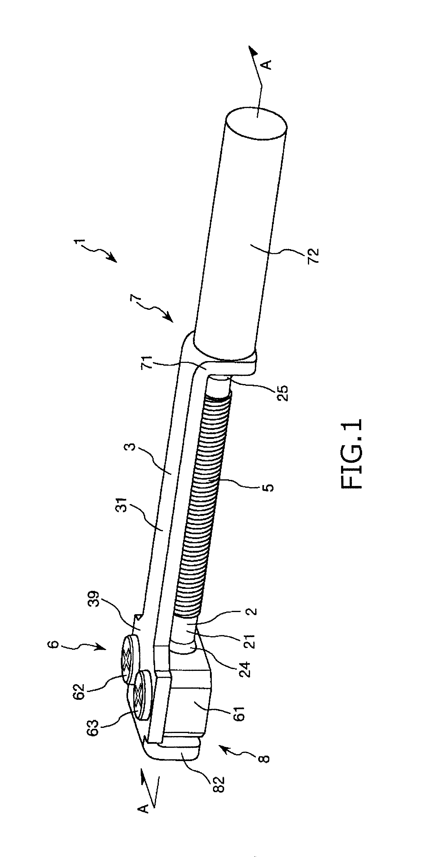
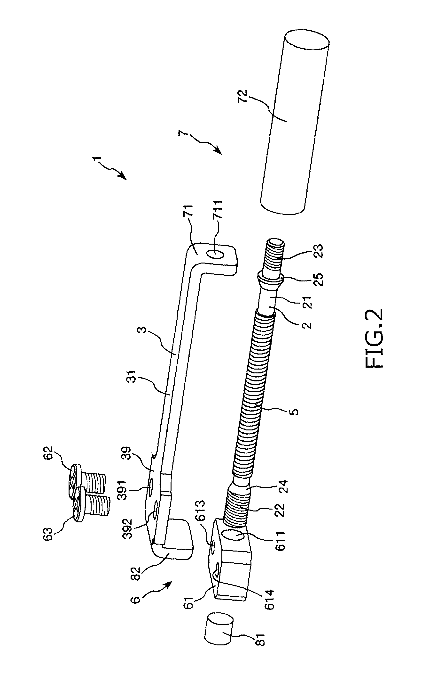
[0043]FIG. 1 is a perspective view showing the power generating element according to the first embodiment of the present invention. FIG. 2 is an exploded perspective view showing the power generating element shown in FIG. 1. FIG. 3 is a vertical cross-sectional view (taken along an A-A line shown in FIG. 1) showing the power generating element shown in FIG. 1.

[0044]Hereinafter, an upper side in each of FIGS. 1 to 3 is referred to as “upper” or “upper side” and a lower side in each of FIGS. 1 to 3 is referred to as “lower” or “lower side”. Further, a right side in each of FIGS. 1 to 3 is referred to as “distal side” and a left side in each of FIGS. 1 to 3 is referred to as “proximal side”.

[0045]A power generating element 1 shown in FIGS. 1 and 2 has a magnetostrictive rod 2 through which lines of magnetic force pass in an axial direction thereof, a magnetic ro...

second embodiment

[0101]Next, description will be given to a power generating element according to a second embodiment of the present invention.

[0102]FIG. 4 is an enlarged view showing a part of a distal side of the power generating element according to the second embodiment of the present invention. Hereinafter, an upper side in FIG. 4 is referred to as “upper” or “upper side” and a lower side in FIG. 4 is referred to as “lower” or “lower side”. Further, a right side in FIG. 4 is referred to as “distal side” and a left side in FIG. 4 is referred to as “proximal side”.

[0103]Hereinafter, the power generating element according to the second embodiment will be described by placing emphasis on the points differing from the power generating element according to the first embodiment, with the same matters being omitted from description.

[0104]A power generating element 1 according to the second embodiment has the same configuration as the power generating element 1 according to the first embodiment except t...

third embodiment

[0108]Next description will be given to a power generating element according to a third embodiment of the present invention.

[0109]FIG. 5 is an exploded perspective view showing the power generating element according to the third embodiment of the present invention. FIG. 6 is a vertical cross-sectional view showing the power generating element shown in FIG. 5.

[0110]Hereinafter, an upper side in each of FIGS. 5 and 6 is referred to as “upper” or “upper side” and a lower side in each of FIGS. 5 and 6 is referred to as “lower” or “lower side”. Further, a right side in each of FIGS. 5 and 6 is referred to as “distal side” and a left side in each of FIGS. 5 and 6 is referred to as “proximal side”.

[0111]Hereinafter, the power generating element according to the third embodiment will be described by placing emphasis on the points differing from the power generating elements according to the first and the second embodiments, with the same matters being omitted from description.

[0112]A power ...


PUM


Abstract

A power generating element includes a magnetostrictive rod through which lines of magnetic force pass in an axial direction thereof, the magnetostrictive rod formed of a magnetostrictive material; a magnetic rod arranged in parallel with the magnetostrictive rod, the magnetic rod formed of a magnetic material; a first coupling mechanism for coupling one end portion of the magnetostrictive rod and one end of the magnetic rod; a second coupling mechanism for coupling the other end portion of the magnetostrictive rod and the other end portion of the magnetic rod; and a coil provided so that the lines of magnetic force pass inside the coil in an axial direction thereof and in which a voltage is generated on the basis of a variation of density of the lines of magnetic force caused when the magnetostrictive rod is expanded or contracted. Further, at least one of the one end portion and the other end portion of the magnetostrictive rod is formed into a male screw portion.

Description

TECHNICAL FIELD[0001]The present invention relates to a power generating element.BACKGROUND ART[0002]In recent years, a power generating element which can generate electric power by utilizing a variation of magnetic permeability of a magnetostrictive rod formed of a magnetostrictive material has been developed (for example, see patent document 1).[0003]For example, a power generating unit (power generating element) described in the patent document 1 includes a rod-like super magnetostrictive member (magnetostrictive rod), two permanent magnets respectively attached to both end portions of the super magnetostrictive member and a coil wound around the super magnetostrictive member. When the super magnetostrictive member is deformed (or compressed) in an axial direction thereof or deformed (or bent) in a direction perpendicular to the axial direction thereof, that is, when expansion and contraction occur in the super magnetostrictive member, magnetic permeability of the super magnetost...

Claims


Application Information

Patent Timeline
Patent Type & Authority Patents(United States)
IPC IPC(8): H01L41/12H02N2/18
CPCH01L41/125H02N2/18H02N2/186H10N35/101
Inventor FURUKAWA, KENICHINUMAKUNAI, TAKAYUKI
Owner MITSUMI ELECTRIC CO LTD
Why Eureka
Try Eureka