Camera and wire feed solution for orbital welder system

a technology of orbital welding and mounting devices, which is applied in the direction of manufacturing tools, metal working equipment, other domestic objects, etc., can solve the problem of limited visibility

Inactive Publication Date: 2016-12-27
LINCOLN GLOBAL INC
View PDF171 Cites 4 Cited by
  • Summary
  • Abstract
  • Description
  • Claims
  • Application Information

AI Technical Summary

Problems solved by technology

With orbital welding often involves limited visibility of a welding zone with lead cameras and / or trailing cameras.

Method used


Image

  • Camera and wire feed solution for orbital welder system
  • Camera and wire feed solution for orbital welder system
  • Camera and wire feed solution for orbital welder system

Examples


Embodiment Construction

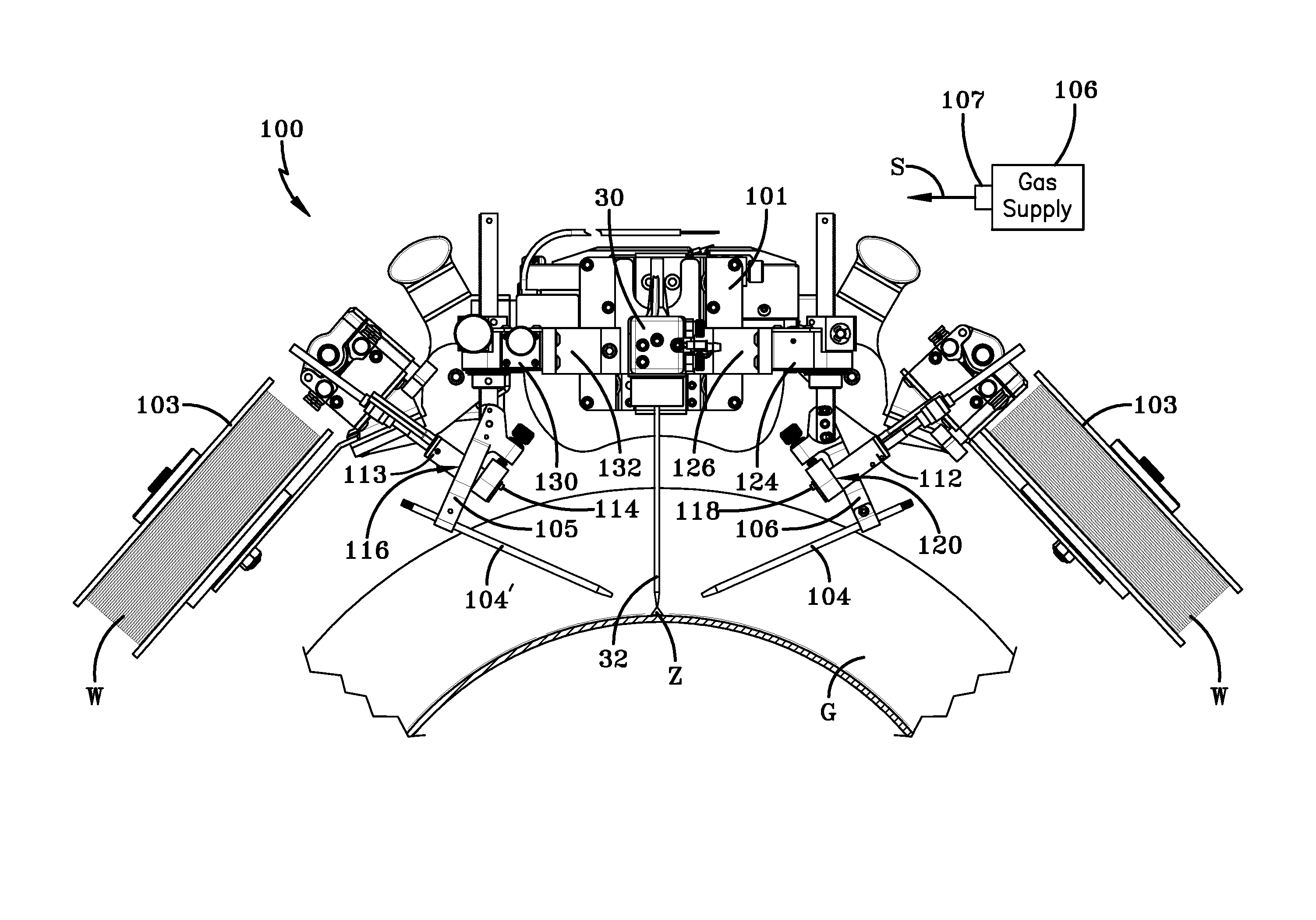
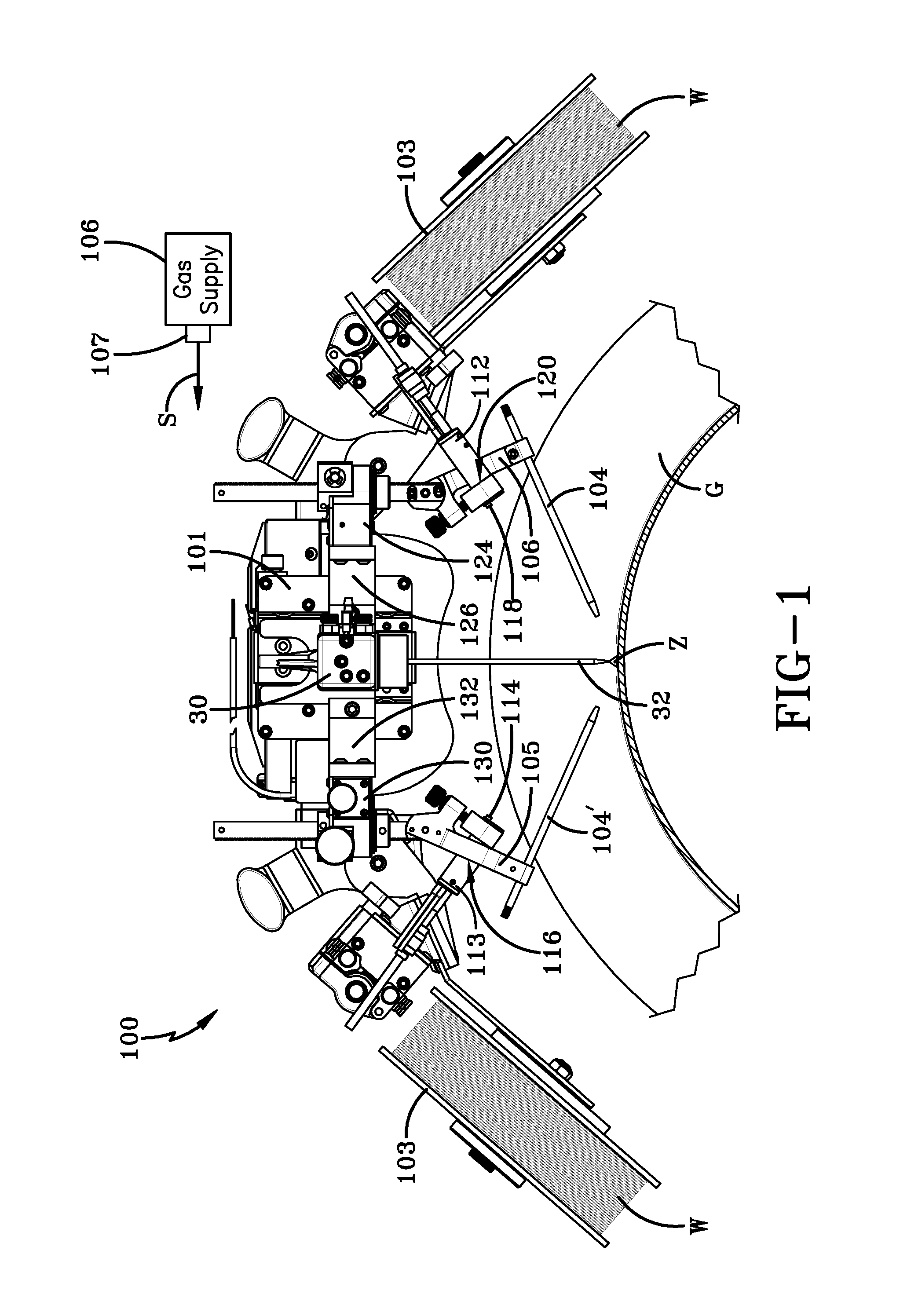
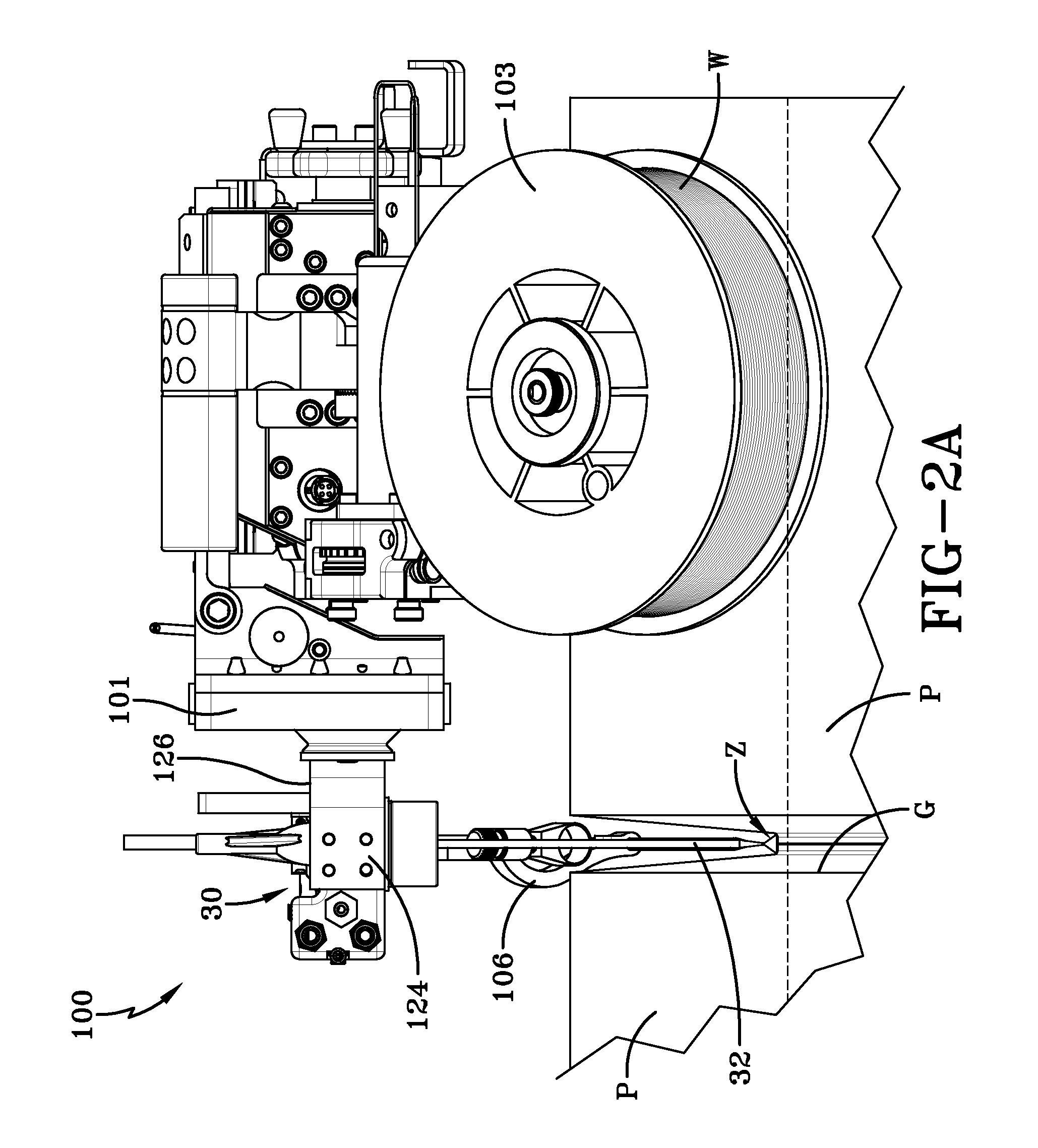
[0018]Embodiments of the invention relate to methods and systems that relate to camera device and wire guide system that includes a bracket for a wire guide and a camera device, wherein the bracket aligns the camera device to aim on a position of a welding zone for an orbital welding system. In particular, the bracket supports a wire guide to be positioned on a welding zone while also supporting a camera device that can be positioned on the welding zone. The bracket enables the welding zone to be captured by the camera device and is centered on the wire guide to remain positioned on the welding zone. The bracket provides placement of a camera device to provide video / camera visibility of the welding zone while allows adjustment of the camera device with wire location adjustment or independent of wire location adjustment. Moreover, a wire guide and camera device system can include a bracket and a height adjustment device that maneuvers the bracket (and affixed camera device and wire g...


PUM

PropertyMeasurementUnit
lengthsaaaaaaaaaa
lengthaaaaaaaaaa
lengthaaaaaaaaaa

Abstract

The technology described herein generally pertains to a system related to a camera device and wire guide system that includes a bracket for a wire guide and a camera device, wherein the bracket aligns the camera device to aim on a position of a welding zone for an orbital welding system. In particular, the bracket supports a wire guide to be positioned on a welding zone while also supporting a camera device that can be positioned on the welding zone. The bracket enables the welding zone to be captured by the camera device and is centered on the wire guide to remain positioned on the welding zone. The bracket provides placement of a camera device to provide video / camera visibility of the welding zone while allows adjustment of the camera device with wire location adjustment or independent of wire location adjustment.

Description

TECHNICAL FIELD[0001]In general, the present invention relates to a camera and mounting device used in connection with an orbital welding system. More particularly, the present invention relates to a camera mounting device that couples to a portion of a welding system while providing versatile adjustment for a camera to focus on a welding zone.BACKGROUND OF THE INVENTION[0002]In industrial applications, welding may involve, raising, cladding, building up, filling, hard facing, overlaying, joining, and other welding applications. When confronted with a workpiece having a curved surface, an orbital welding processes may be used to rotate the welding head to apply a weld to the curved surface. The most common examples, where orbital welding is used, is the welding of pipe. Pipe welding may include thin wall application where the welding head is rotated about the other surface two piece ends being joined together, alternatively, pipe welding may include deep grove geometries where the w...

Claims


Application Information

Patent Timeline
Patent Type & Authority Patents(United States)
IPC IPC(8): B23K9/095B23K9/12B23K9/32B23K9/028
CPCB23K9/0956B23K9/0286B23K9/122B23K9/32B23K2201/06B23K2101/06
Inventor MILLER, VICTOR
Owner LINCOLN GLOBAL INC
Why Eureka
Try Eureka