
Starter motor control with pre-spin

a technology for starting motors and control circuits, which is applied to engine starters, power operated starters, machines/engines, etc., can solve problems such as electromagnetic interference, interference with electrical control circuits within the vehicle, and further reduction of the starting current available from cold batteries

Active Publication Date: 2016-12-27
FORD GLOBAL TECH LLC
View PDF22 Cites 0 Cited by
  • Summary
  • Abstract
  • Description
  • Claims
  • Application Information

AI Technical Summary

Benefits of technology

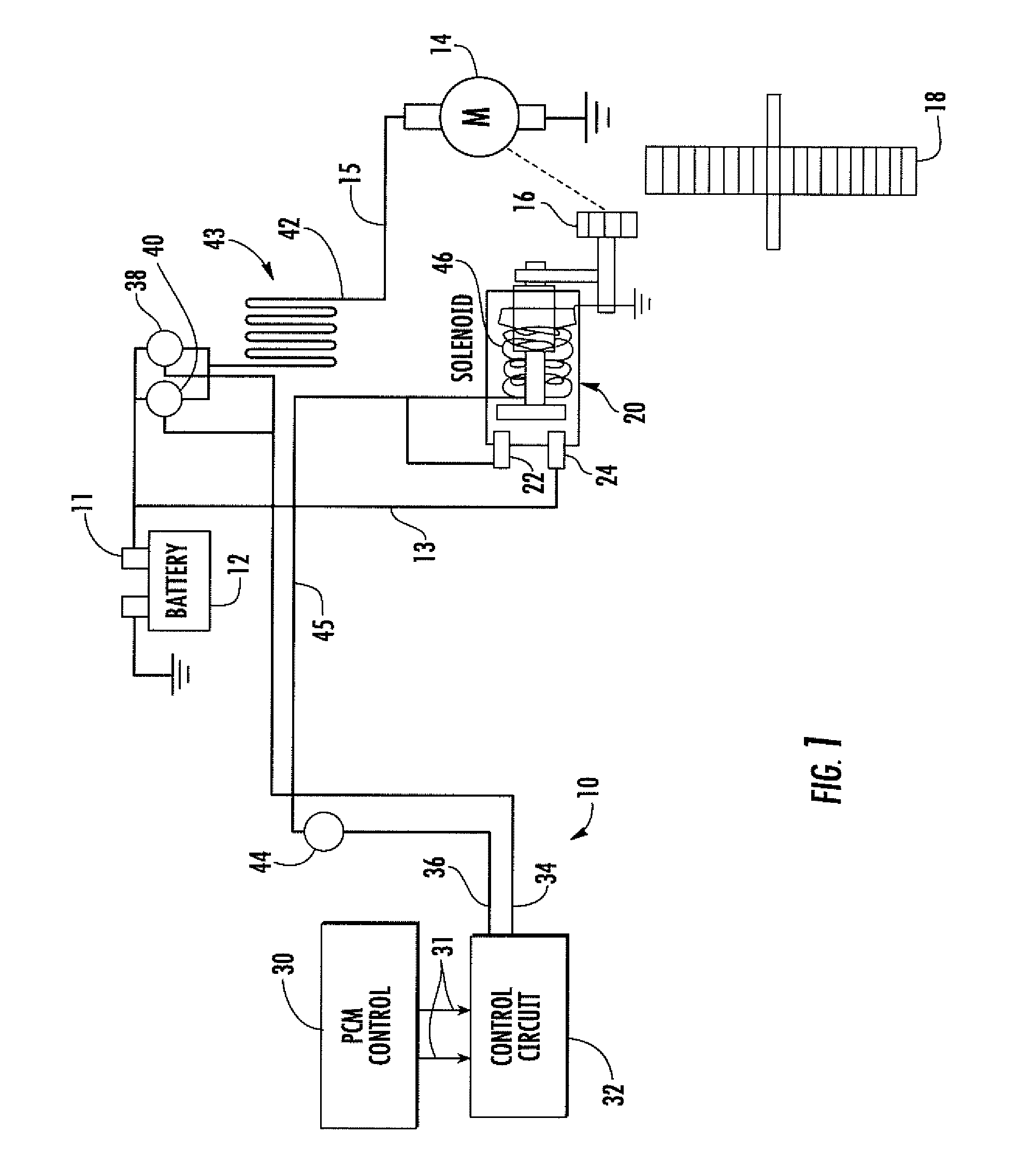
[0003]The system of the present invention accomplishes this goal by providing a control circuit receiving starting signals from a power control module of the vehicle and delaying the coupling of the main starting current from the battery to the starting motor until a reduced current in an alternate flow path is provided to the starter motor, initiating its motion. In a preferred embodiment of the invention, the desired pre-start sequence is controlled by a microprocessor which provides a control signal to a solid state switch coupled by a conductor providing current limiting resistance between the battery supply and the starter motor for a predetermined period of time. Subsequent to this pre-spin period, the control circuit provides a signal to a different solid state switch which activates the starter solenoid, in turn, coupling the battery to the starter motor and engaging the pinion gear with the ring gear. This sequence of operation provided by the control circuit assures the vehicle engine is started with the minimum of battery current drain and wear on the starting pinion gear and is accomplished in a relatively inexpensive control circuit which does not adversely affect other electrical circuits within the vehicle.

Problems solved by technology

This problem is particularly acute in Stop / Start vehicles, where the battery goes through significant cycling and is near the end of life, also in winter months where the starting current available from a cold battery is further reduced.
Such an approach, however, potentially creates electromagnetic interference issues, which can interfere with electrical control circuits within the vehicle.
Also, with some diode-driven techniques, accidentally coupling the battery in reverse polarity can short the circuitry, causing damage to the starting circuit.

Method used


Image

  • Starter motor control with pre-spin
  • Starter motor control with pre-spin
  • Starter motor control with pre-spin

Examples


Embodiment Construction

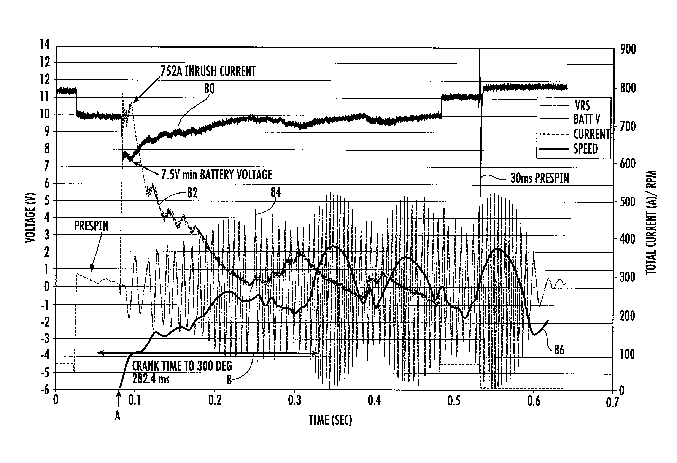
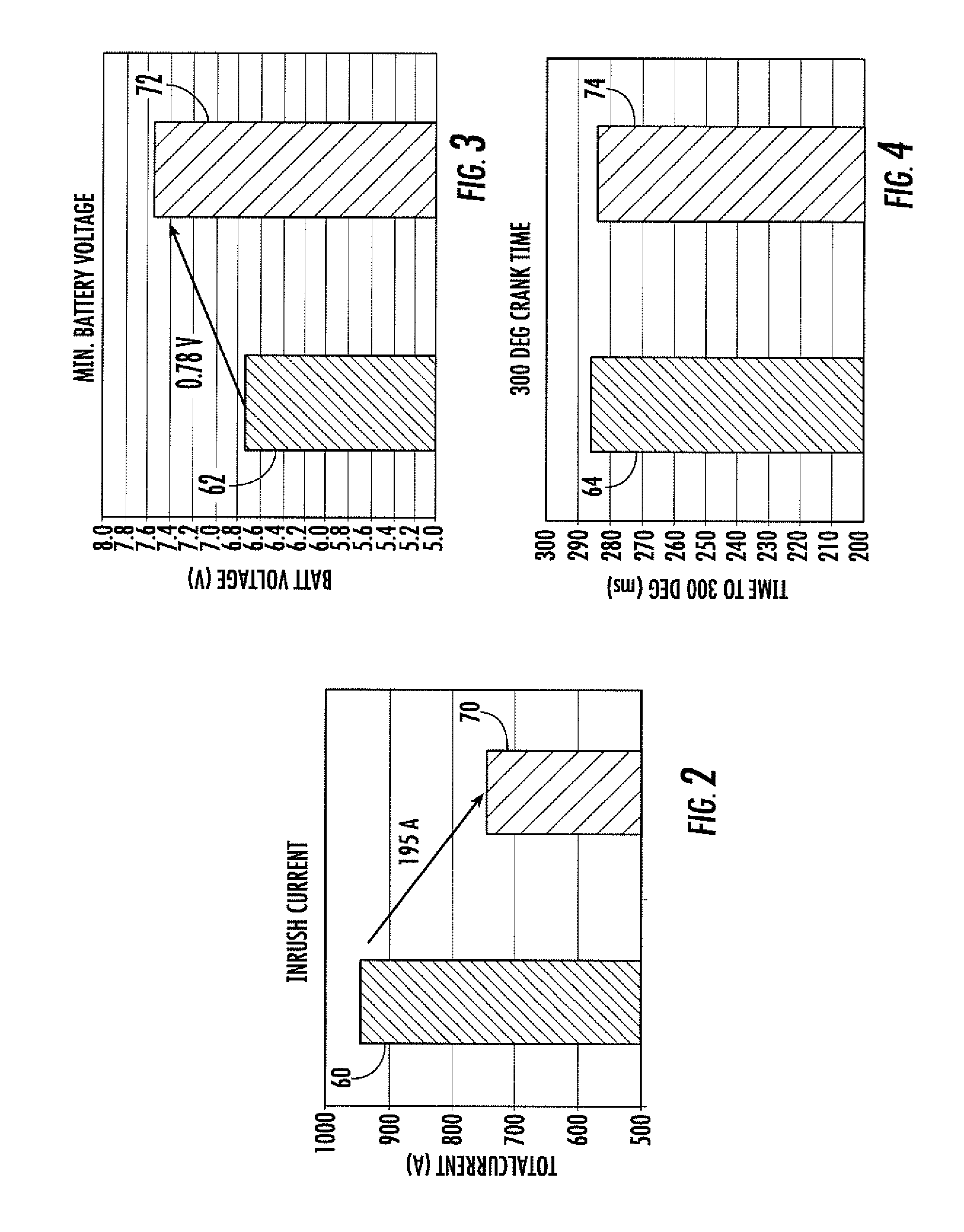
[0012]Referring initially to FIG. 1, there is shown the system of the present invention in an electromechanical schematic / block diagram form. The control system 10 is employed for controlling the current from the vehicle's battery 12 to the starting motor 14, which, in turn, is coupled to a pinion gear 16 which selectively engages the ring gear 18 of the vehicle's powertrain. In a typical starting circuit, the battery would be coupled to the coil 46 of the starting solenoid 20 which engages contacts 22, 24 to supply current from battery 12 through conductors 13 and 15 directly to the starting motor 14. When activated, the solenoid 20 also moves the pinion gear 16 into meshing engagement with ring gear 18. This normal sequence requires a significant amount of inrush current. As illustrated by the bar graph 60 shown in FIG. 2, the current can range in the neighborhood of from about 900 to nearly 1000 amps, which drops the battery voltage from a normal 12 volts to frequently below 7 vo...


PUM


Abstract

A control circuit receives a starting signal from a powertrain control module of a vehicle and delays the coupling of the main starting current from the battery to the starting motor until a reduced current in an alternative flow path is provided to the starter motor, initiating its motion. In a preferred, the pre-start sequence is controlled by a microprocessor which provides a control signal to a solid state switch coupled by a conductor providing current limiting resistance between the battery supply and the starter motor for a predetermined period of time. Subsequent to the pre-spin period, the control circuit provides a signal to a different solid state switch which activates the starter solenoid, in turn, coupling the battery to the starter motor and engaging the pinion gear with the ring gear.

Description

FIELD OF THE INVENTION[0001]The present invention relates to a control circuit for a vehicle starting motor.BACKGROUND OF THE INVENTION[0002]When cold cranking a vehicle engine, the inrush current as the vehicle battery is coupled to the starting motor can be very significant, in the neighborhood of 900-1000 amps. Such starting current can, under some conditions, drop the battery voltage sufficiently to reset electrical systems in the vehicle. This problem is particularly acute in Stop / Start vehicles, where the battery goes through significant cycling and is near the end of life, also in winter months where the starting current available from a cold battery is further reduced. Some efforts have been made to minimize these undesirable starting problems by, for example, pulse width modulating the current applied to the starting motor. Such an approach, however, potentially creates electromagnetic interference issues, which can interfere with electrical control circuits within the vehi...

Claims


Application Information

Patent Timeline
Patent Type & Authority Patents(United States)
IPC IPC(8): F02D17/00F02N11/08
CPCF02N11/0814F02N11/0844F02N11/0851F02N11/0855F02N2011/0874F02N2250/02F02N2300/106Y02T10/48Y02T10/40
Inventor LIU, XIANGYINGDE BIASI, CHUCKATLURU, RAVISHELL, FREDERICKJUDGE, ALAN FRANCISALLES, SHERAN ANTHONY
Owner FORD GLOBAL TECH LLC
Learn More