Image forming apparatus with cartridge supporting movable member
a technology of forming apparatus and movable member, which is applied in the direction of electrographic process apparatus, instruments, optics, etc., can solve the problems of difficult to ensure the mounting locus, and achieve the effects of shortening the fpot, improving usability, and reducing the size of the main assembly of the apparatus
- Summary
- Abstract
- Description
- Claims
- Application Information
AI Technical Summary
Benefits of technology
Problems solved by technology
Method used
Image
Examples
embodiments 1 and 4-6
(2) Embodiments 1 and 4-6
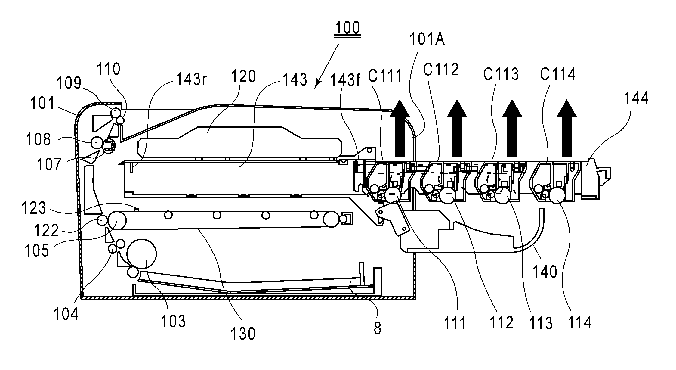
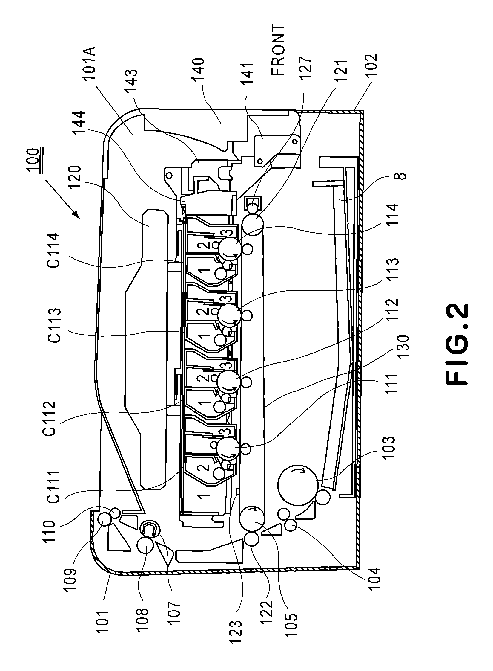
[0287]The movable members include the first guiding portions (146c-147c, 148b), the second guiding portions (145c-147c) and the engaging members (161, 461, 561, 661).
[0288]Each of the first guiding portions is engageable with one of the pair of adjacent cartridges. Each of the second guiding portions is engageable with the other cartridge and is capable of guiding the other cartridge so that the other cartridge is movable in the arranging direction in a distance larger than the first guiding portion.
[0289]Each of the engaging members is engageable with at least the other cartridge and is provided movably on the movable member so that the other cartridge is moved along the second guiding portion by the movement of the movable member from the inside position to the outside position.
(3) Embodiment 1
[0290]The second guiding portions (145c-147c) are positioned upstream of the first guiding portions (146c-147c, 148b) with respect to the pulling-out direction of th...
embodiment 1
(4) Embodiment 1
[0291]The second guiding portions are connected with the guiding portions (145a-148a) for mounting and dismounting the other cartridge, in the upstream side of the pulling-out direction, relative to the movable member in the direction crossing the arranging direction.
(5) Embodiments 4-6
[0292]Each of the second guiding portions is positioned downstream of the associated first guiding portion with respect to the pulling-out direction of the movable member, and has the arcuate shape extending in the arranging direction.
embodiments 4-6
(6) Embodiments 4-6
[0293]The second guiding portions are connected with the third guiding portions (445a-448a, 545a-548a, 645a-648a) each for mounting and dismounting the other cartridge relative to the movable member with respect to the direction crossing the arranging direction.
(7) Embodiments 2-3 and 7-8
[0294]The movable members include the first mounting portions (344(1), 744A, 844A, etc.) each for supporting one of the pair of adjacent cartridges and the second mounting portions (344(2), 744B, 844B, etc.) each for supporting the other cartridge. Further, by the movement of each of the movable members from the inside position to the outside position, the distance between the first mounting portion and the second mounting portion is constituted so as to be increased.
PUM
 Abstract
Description
Claims
Application Information
 - R&D
- Intellectual Property
- Life Sciences
- Materials
- Tech Scout
- Unparalleled Data Quality
- Higher Quality Content
- 60% Fewer Hallucinations
Browse by: Latest US Patents, China's latest patents, Technical Efficacy Thesaurus, Application Domain, Technology Topic, Popular Technical Reports.
© 2025 PatSnap. All rights reserved.Legal|Privacy policy|Modern Slavery Act Transparency Statement|Sitemap|About US| Contact US: help@patsnap.com


